5
Visit
help.c5k.info
for more information and support
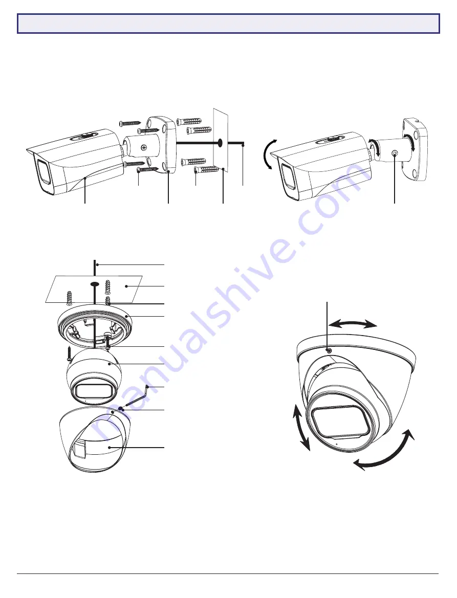
Fig. 2.1:
Mounting diagram for fixed bullet
Camera
Base
Surface
Cables
Self-tapping
screws
Wall plugs
Fig. 2.3:
Mounting diagram for fixed dome
Surface
Wall plugs
Self-tapping screws
Camera
Enclosure
Locking screw
Allen key
Pedestal
Fig. 2.4:
Tri-axis fixed dome adjustment
Fig. 2.2:
Tri-axis fixed bullet adjustment
Locking screw
Locking screw
Cables
NOTE:
Diagrams shown below assume camera to be mounted on masonry. Cameras mounted on drywall (gyprock,
plasterboard, etc.) will require special mounting screws or toggles (not included).
Diagrams are examples only - screws and other physical components may vary depending on your camera model(s).
2.2 Mounting Surveillance Cameras (continued)


