5
Flashing with a short pulse every second:
- Correct power supply and serial communication.
4.2 Tamperproof protection
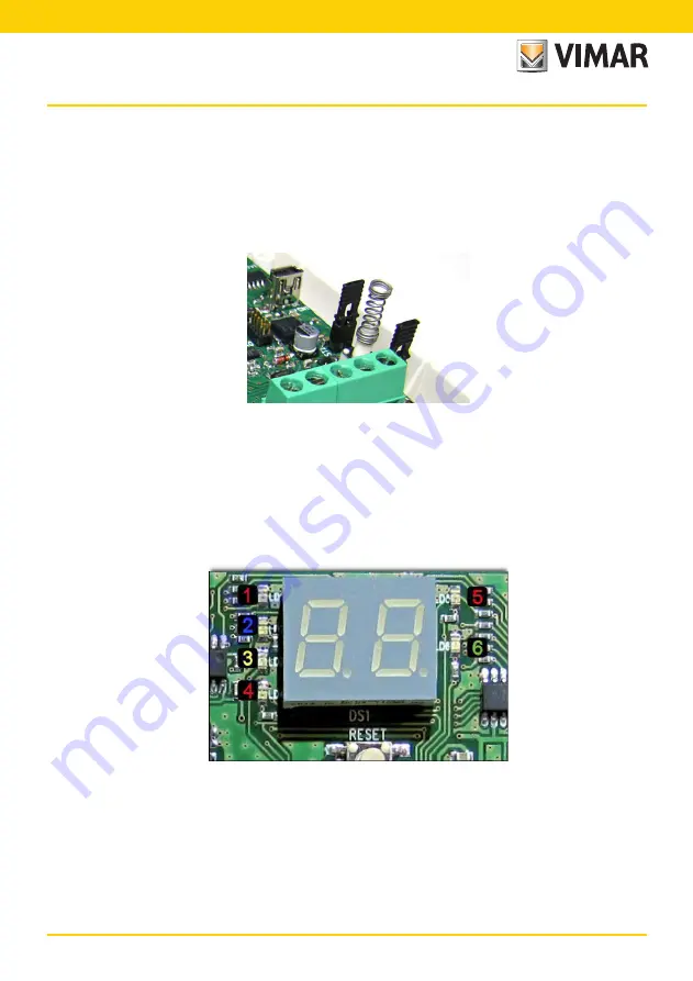
The board has 2 push-buttons to protect against enclosure opening and against tearing it off the wall that can
be excluded by closing the relevant jumpers under the push-buttons themselves.
Keying in the Installer Code inhibits every kind of alarm, and thus also all the tamper-proof protections will be
blocked.
When commissioning the control panel, the cut-off jumpers
ST1
and
ST2
of the tamper-proof protections must
be removed to make the protections active.
4.3 Function LEDs
On the board there are six LEDs and a display that shows the various states of the interface.
During normal operation, the LEDs are off and the display cyclically shows the various associated devices.
In the event of an alarm and/or malfunctioning of a device, the interface will immediately display the number of
the relevant device and one of the LEDs on the left of the display will light up to indicate its cause.
If multiple devices were simultaneously in an alarm and/or fault status, the interface display would cycle through
the states of the various devices concerned.
By-alarm
Features of the radio interface


