3
2. Installing the radio interface
When securing the radio interface and to improve its operation, follow these instructions:
• do not remove the circuits from the plastic enclosure.
• do not install near metal objects and devices that generate radio frequencies (televisions, computers, routers,
hot spots, etc.)
• install at a height of not less than 1.5 m off the ground in a location as central as possible to the position of the
devices.
• install with the terminals facing downwards and the aerial set in a vertical position.
• cable entry must be as far away from the aerial as possible and, therefore, from the bottom side using the holes,
making sure that they do not overlap it.
2.1 Connection
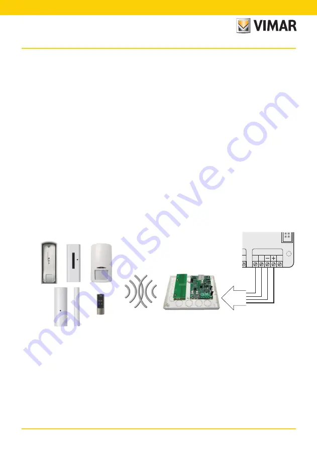
The radio interface with 8 or 16 input lines, in a self-protected plastic enclosure, is connected to the control
panel to one of the branches of the RS485 serial ports like any serial device, following the instructions given in
the control panel installation manual, respecting their abbreviations.
So, 2 conductors carry the power supply positive and negative, and another two the connections A and B
referring to the signals.
For the 12 V- power supply it is necessary to use conductors of at least 0.50 mm
2
and of 0.22 mm
2
for the
signals; the shielding must be connected to the negative terminal on the control panel side and left free on
the interface side.
CN5
20
D
E
A B
RS 485
By-alarm
Installing the radio interface


