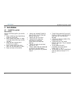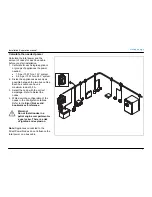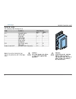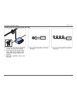
Installation & operation manual
5
victr on ener gy
B L U E P O W E R
1.3 Overview
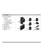
Overview of components
A. Cable harness including:
•
10 A fuse
•
50 A fuse
•
10 A. direct power node
•
20 A. direct power node
•
2 × 15 m. bus cable
•
8 m cable for push button panel
•
8 m cable for bilge-pump
•
8 m cable for instruments
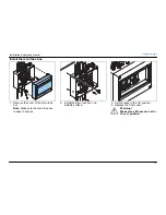
B. Push button panel
C. 3 A. power nodes
D. 10 A. power nodes
E. 16 A. power nodes
F. Sensor node for bilge-pump
G. Cable cutter
H. DC 4 compound (tube)
I. CD
labels
B(1x)
A(1x)
C(5x)
16
10
3
G(1x)
I(1x)
H(1x)
D(8x)
E(2x)
F(1x)
S


