background image


22

1. Manual operation  


For the boiler ignition it is necessary to operate manually the fuel 

conveyor and ventilator. For this purpose there serve the pushbuttons 

1


and 

2

. Pushbutton 

1

 operates the ventilator, pushbutton 

2

 the fuel 

conveyor. By pressing the relevant unit is switched on and by repeated 
pressing the relevant unit is switched off. The ventilator operation is 
displayed by burning line(stroke) under the ventilator symbol. Once the 
ventilator stops the line goes out. The same applies to the fuel conveyor operation indication. It is indicated 
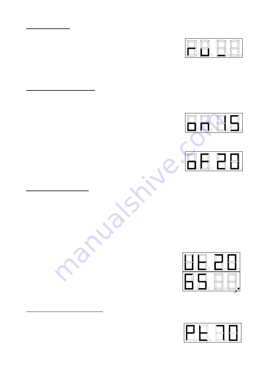
by a line(stroke) under the fuel symbol. The fact that the boiler is manually operated is indicated on display 
by abbreviation 

ru

 and burning stroke at the notice 

„manual“.


2. Fuel conveyor cycles setting  


For a correct boilers function it is necessary to set an optimal proportion between 

the time for fuel 

feeding

 (conveyor works) and the 

time for


fuel afterburning 

(conveyor in resting stage)  


a)  By pressing the pushbutton 

4

 there appears on display the data like 

on 

15

 and it means the operation of fuel reservoir screw conveyor 

15


(combustion chamber screw conveyor works parallel, but incl. after-
running). The value can be changed by pressing the pushbutton 

*

 and 

entering a new digit combination like 

20

. Then 

oF 20

 is alight on 

display

.

 The decision correctness must be confirmed by pushbutton 

*

Confirmation 

o.k. 

must appear on display

.

 The fuel feeding time can be set within 

3 - 90

 s, see tab. no.5. 


b)  By pressing the pushbutton 

5

 there appears on display the data like 

oF 

20

 and it means that the conveyor is in a resting state for 

20

 s. The 

value can be changed by pressing the pushbutton 

*

 and entering a 

new digit combination like 

30

. Then 

oF 30

 is alight on display

.

 The 

decision correctness must be confirmed by pushbutton 

*

. Confirmation 

o.k. 

must appear on display

The after-combustion time can be set within 

3 - 90

 s, see tab. no.5. 


3. Inhibition duration setting  


If the heating water outlet temperature has exceeded the set limit the regulator will shut down the fuel 

feeder and ventilator until the temperature drops below the set limit with hysteresis -3 °C. It could happen 
that this time is too long and the boiler burns out. That’s why there is set the maximum shut down time so 
called. 

inhibition duration. 

Once it has passed over the ventilator and fuel conveyor start up automatically 

within 2 minutes, independently on heating water outlet temperature. Then the regulator comes back into 
inhibition status and follows the heating water outlet temperature. The circulating pump is constantly 
switched on. The same can be induced by indoor thermostat once the room temperature has been 
exceeded. Then besides the induction into the inhibition status there is switched off the circulating pump 
while keeping the 4 minutes after-running. 

By pressing the pushbutton 

6

 there appears on display the data like 

Ut 20

 and it means the 

20

 minutes 

inhibition duration. The value can be changed by pressing the 
pushbutton 

*

 and entering a new digit combination like 

30

. Then 

oF 30

 is 

alight on display

.

 The decision correctness must be confirmed by 

pushbutton 

*

. Confirmation 

o.k. 

must appear on display

The inhibition 

duration can be set between 

5 and 90

 minutes. Recommended value is 

30

 min. If in this regime the heating water temperature significantly rises 

(first of all in summer season, when there is a minimum heat take-off 
from the system), it is recommended to increase this value. 
Inhibition on display is indicated by a burning point in its right lower 
corner.  

 
4. Outlet water temperature setting 


The required outlet water temperature


is set by means of pushbutton 

3

. On display there appears the 

data like 

Pt 70

 and it means the required outlet water temperature of 

70


°C. The value can be changed by pressing the pushbutton 

*

 and entering 

a new digit combination like 

75

. Then 

Pt 75

 is alight on display. The 

decision correctness must be confirmed by pushbutton 

*

. Confirmation 

o.k. 

must appear on display

.

 The required outlet water temperature can 

be set between 

60 and 90

 °C. It is recommended to operate boiler at temperatures higher than 

65 

°C. 


Indikace útlumu

Inhibition 

Содержание HERCULES ECO 10

Страница 1: ......

Страница 2: ...tallation 13 6 2 Boiler shells and regulator assembly 14 6 3 Fuel reservoir assembly this part is delivered optionally 15 6 4 Assembly of combustion chamber and the fuel transport lines 16 6 5 Filling...

Страница 3: ...ade name is VIADRUS HERCULES ECO The boiler is manufactured as in warm water design with forced heating water circulation and operating overpressure up to 400 kPa Before dispatch it is checked for tig...

Страница 4: ...4 Fig no 1 VIADRUS HERCULES ECO with fuel reservoir front view left version Fig no 2 VIADRUS HERCULES ECO with fuel reservoir rear view left version...

Страница 5: ...0 1940 x 1405 x 1615 Maximum water operating overpressure kPa 400 Testing water overpressure kPa 800 Heating water minimum temperature C 60 Heating water maximum temperature C 90 Chimney draught Pa 15...

Страница 6: ...an doors the combustion chamber door is behind them The whole boiler drum is insulated by using a health harmless mineral insulation which reduces the heat interchange losses in surroundings The steel...

Страница 7: ...7 Fig no 3 VIADRUS HERCULES ECO boiler dimension dimensions behind the slash apply to 10 sectional size...

Страница 8: ...Central section Boiler insertion Rear section Three figure reservoir Heating water flange Smoke adapter Straight sleeve of the smoke adapter Smoky flap Lever Clearing cover of the smoke Opening for co...

Страница 9: ...hen the building isn t used information about the real and required temperature in the room ATTENTION For boiler control there can only be used the free potential free contact switching voltage is 5 V...

Страница 10: ...ing 1 pc thermomanometer 1 pc logo VIADRUS 1 pc SK strip 70 90 2 pc Heating water flange 1 pc Return water flange 1 pc sealing 90x60x3 mm 2 pc elbow 1 2 1 pc filling and discharging cock 1 2 1 pc clea...

Страница 11: ...test data from reaction to fire tests d to the electrical network SN 33 0165 Electrical regulations Marking the conductors with colours or digits Implementing regulations SN 33 1500 Electrical regula...

Страница 12: ...m The safe distance is to be doubled also in case that the combustibility degree of building material wasn t proved Tab no 2 Combustibility degrees of building materials and products Combustibility de...

Страница 13: ...nd as close as possible to boiler Fig no 6 Positioning of VIADRUS HERCULES ECO boiler in boiler room dimension behind the slash applies to 10 sectional size 6 Boilers assembly 6 1 Boiler drum installa...

Страница 14: ...able 2 m possibly the pump cable and indoor thermostat cable to the regulator Insert the whole into the opening in the middle part of boiler shell upper part after having removed the insulation before...

Страница 15: ...o this whole screw on gradually the side and leg of fuel reservoir 3 Set together in a similar way other 3 vertical walls of fuel reservoir 4 Cover the whole with the fuel reservoir cover Note Alterna...

Страница 16: ...locks Possible leakage can be sealed by sealing cement with resistance up to 1200 C like ZWALUW or heat resisting concrete 4 Through the stoking door insert into the convection part of cast iron heat...

Страница 17: ...rom movement we recommend at the assembly to bore together the ventilator with the sleeve and secure it with a bolt or rivet 7 To carry out the electric interconnection of engines and ventilator with...

Страница 18: ...system must be kept constant When refilling the heating system it has to be prevented from air intake Water from boiler and heating system must never be discharged or taken for usage except for the em...

Страница 19: ...C 6 5 4 8 7 2 1 3 STOP Inhib manual automat Functions on keyb Emergency thermostat 6 max inhib time 7 ventilator drifting setting START automat 1 2 STOP automat 1 ventilator 2 fuel feeder 3 req outle...

Страница 20: ...0 V 2 A ventilator 230 V 2 A circulating pump 230 V 2 A Steady set parameters Pump min 4 ventilator after running s 5 99 conveyor continuous operation min max 10 Automatic operation after inhibition m...

Страница 21: ...X regulator for motors with thermal protection Wiring diagram of RKU 2 for motors with thermal protection Note To the connectors TP motor 1 and 2 thermal overload motor protection no voltage must be b...

Страница 22: ...exceeded the set limit the regulator will shut down the fuel feeder and ventilator until the temperature drops below the set limit with hysteresis 3 C It could happen that this time is too long and th...

Страница 23: ...er Note During the boiler commissioning process and after the regulator has been switched on or occasionally already during the boiler automatic operation there flickers on display the message Er but...

Страница 24: ...t of starling flap of the fan on nr 7 5 85 30 3 8 5 71 25 2 5 9 5 62 20 2 10 5 55 35 3 5 11 5 49 40 4 12 5 44 45 4 5 13 5 40 50 5 14 5 37 50 5 15 5 34 55 5 5 16 5 32 60 6 17 5 29 65 6 5 18 5 27 70 7 1...

Страница 25: ...10 27 80 8 38 10 26 85 8 5 39 10 25 85 8 5 40 10 24 90 9 41 10 24 90 9 42 10 23 95 9 5 0 10 20 30 40 50 60 70 80 90 10 15 20 25 30 35 40 45 50 V kon kotle kW as pro doho v n paliva s Picture nr 20 Boi...

Страница 26: ...ture set on the control thermostat has been achieved the boiler operation will become automatic with set air and fuel supply Then the boiler automatically will pass into inhibition regime where it wil...

Страница 27: ...chanism and other movable parts on boiler The boiler room must be kept clean and dry It is forbidden to interfere with boiler structure and electric installation boilers WARNING A poor quality of fuel...

Страница 28: ...boiler drum 5 years after the date its dispatch from the manufacturing factory The user is obliged to entrust an assembly firm with boiler installation and a special contracting service accredited by...

Страница 29: ...unit EN 13429 2000 NO 3 1 Recovery by material recycling ensure recyclability in all term sof the standard for the functional packaging unit EN 13430 2000 YES 3 2 Recovery in the form of energy ensure...

Страница 30: ...30...

Страница 31: ...31...

Страница 32: ...32...

Страница 33: ...uding the standard accessories and output set according to Operation and installation manual is guaranteed by manufacturer through the contracting service organization The guarantee certificate isn t...

Страница 34: ...34...

Страница 35: ...eness including the standard accessories and output set according to Operation and installation manual is guaranteed by manufacturer through the contracting service organization The guarantee certific...

Страница 36: ...36...

Страница 37: ...including the standard accessories and output set according to Operation and installation manual is guaranteed by manufacturer through the contracting service organization The guarantee certificate is...

Страница 38: ...38...

Страница 39: ...certificate for customer the user Record of accomplished guarantee and after guarantee repairs and regular product checks Record date Carried out activity Contracting service organization stamp signa...

Страница 40: ...40 Date of revision 18 2009 SD GB...

Отзывы: