background image

36 

Chapter 3 Web Interface of RDU501 

RDU501 Intelligent Monitoring Unit User Manual 


After modifying the device information, you need to click the 

Save Configuration 

button to make the configuration 

take effect. After clicking 

Save Configuration

, the User Security Verification dialog box pops up, prompting you to 

enter the current user's login password. After entering the correct password, click the 

OK 

button to complete the save 

operation. 


Note 

1.


The IPMI device specifically refers to an IT device accessed through the IPMI 2.0 protocol, and its accessibility and 

communication stability are related to the support capabilities of the IT device itself. 
2.


The device IP address is not allowed to be duplicated. When modifying device information, you cannot modify the IP address. 

3.


If you have not modified any device information, you cannot click the 

Save Configuration 

button. 

4.


After modifying the device information, if you leave the page without clicking the 

Save Configuration 

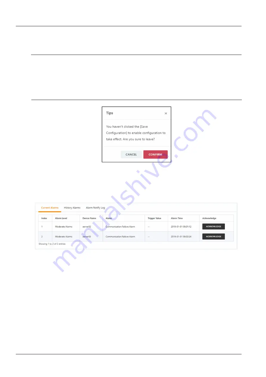
button, a prompt box 

as shown in Figure 3-41 will pop up asking if you want to confirm leaving the page. Clicking the 

Cancel 

button will leave the 

current page, and clicking the 

OK 

button will leave the page and ignore the modification information. 


3. IPMI device alarm 

Figure 3-41 Prompt box for not saving configuration 

Click the 

IPMI Device Alarm 

submenu under the 

IT Management 

menu. The IPMI device alarm page contains three 

tabs: active alarm, historical alarm, and alarm notification log, as shown in Figure 3-42. 
Click the 

Alarm Confirmation 

button to confirm the alarm. After the alarm is confirmed, the alarm notification will not 

be sent. When the mouse cursor is hovering over the 

Confirmed 

text, the alarm confirmation message will be 

displayed in a floating manner, and the mouse cursor will disappear automatically after being removed. 

Figure 3-42    IPMI active alarm 

Click the 

Historical Alarms 

tab to display the page shown in Figure 3-43. Select the device name, start time, and 

end time. Click the 

Query 

button to query the historical alarm of the selected device. 

Содержание RDU501

Страница 1: ...chnical support Users may contact the nearest Vertiv local sales office or service center Copyright 2019 by Vertiv Co All rights reserved The contents in this document are subject to change without no...

Страница 2: ...hods tools and materials to be used in performing procedures not specifically described in this document This document may contain confidential and or proprietary information of Vertiv Group Corporati...

Страница 3: ...l RDU501 Main Unit 11 2 2 1 Mechanical installation 11 2 2 2 Electrical connection 11 2 3 Install Accessories of Expansion Card and Sensor 12 2 3 1 Install expansion card 12 2 3 2 Install intelligent...

Страница 4: ...nagement 48 3 4 6 Data Management 50 3 4 7 Smart Solution Modeling 63 3 4 8 Configuration Management 71 3 4 9 System setting 89 Chapter 4 Maintenance 101 4 1 Restore Default Settings 101 4 2 Troublesh...

Страница 5: ......

Страница 6: ......

Страница 7: ...RDU501 description of parts main functions and technical specifications 1 1 Description of Parts RDU501 includes RDU501 main unit and optional EXP8COM card EXP8DIAI card EXP8DOAO card EXP2DI6DO card S...

Страница 8: ...ed Green No alarm Red Alarm COM Sensor Green Blink Receiving data Off No data received Yellow Blink Transmitting data Off No data transmitted DI AI DO AO Smoke Green On External device is connected Of...

Страница 9: ...5 interfaces The location is shown in Figure 1 1 The parameters are shown in Table 1 7 Table 1 7 Electrical parameters of sensor port Silk Screen Printing Definition Rated Output Voltage Output Curren...

Страница 10: ...reen Blink Receiving data Off No data received Yellow Blink Transmitting data Off No data transmitted EXP8DIAI card optional The EXP8DIAI card provides eight digital or analog input interfaces digital...

Страница 11: ...le 1 13 Definitions of the ports of the EXP2DI6DO card Port name Port type Silk Screen Printing Definition Digital input 1 2 RJ45 port DI1 DI2 Digital input potential free dry contact Digital output 1...

Страница 12: ...l alarm Query historical alarms and view historical alarm reports in graph form Device data 1 Query device main data 2 Download device MIB file 3 Asset information data Historical data 1 Query histori...

Страница 13: ...n Calibrate the RDU501 real time clock Restore defaults Restart RDU501 and restore default configuration Site information settings Modify site information online Authorization code management Extend R...

Страница 14: ...port connection contact Standard Category 5 twisted pair 100 16 2 DI port connection contact Standard Category 5 twisted pair 100 4 3 DO port connection contact Standard Category 5 twisted pair 100 2...

Страница 15: ...a total of 36 COM ports it is recommended that each COM port connects to the same device type 6 Networking through the network TCP IP SNMP the standard supports the connection of 32 intelligent devic...

Страница 16: ...f static electricity the following measures are required Maintain proper temperature and humidity in the device room see Table 1 16 Before the human body touches the circuit board wear an anti static...

Страница 17: ...es of the RDU501 main unit as shown in Figure 2 1and Figure 2 2 1 1 M4 countersunk screws 6 PCS 2 Mounting ears 2 PCS Figure 2 1 Install the mounting ears in the frontside 1 M4 countersunk screw 6pcs...

Страница 18: ...ll expansion card The expansion cards include EXP8COM EXP8DIAI EXP8DOAO and EXP2DI6DO The installation procedures are as follows Remove the baffles of the expansion slots Slot1 Slot2 Slot3 or Slot4 on...

Страница 19: ...User Manual IRM S04DIF can be found in the IRM S04DIF RJ45 Port Intelligent Digital Input Sensor User Manual IRM S04DO can be found in the IRM S04DO Phoenix Port Intelligent Digital Output Sensor User...

Страница 20: ...the RDU501 through the IRM S04DI or IRM S04DIF Connect the sensor to the IRM S04DI or IRM S04DIF Digital input port For the wiring sequence refer to the IRM S04DI Phoenix Port Intelligent Digital Inpu...

Страница 21: ...upport mainstream web browsers such as Google Chrome Firefox Safari Internet Explorer 11 Edge etc 3 2 Login RDU501 3 2 1 Authorized Startup 1 When logging in to the RDU501 for the first time open the...

Страница 22: ...he Login button which will open the home page as shown in Figure 3 4 Note 1 After logging in to the system for the first time it is recommended to change the default password of thesystem 2 It is reco...

Страница 23: ...umber of real time alarms 6 Controllable status 7 User name 8 Logout current user 9 Fold submenu button 10 Menu item 11 System Time and time calibrating link 12 Hot and cold aisle temperature 13 Real...

Страница 24: ...t side of the line to cancel the addition after selecting the device name and signal name click theOK icon on the right side of the line to complete the addition of the line When the addition is compl...

Страница 25: ...lick the OK button the home page will display the background image Click the Browse button to select the background image After selecting the image file click the Upload button and the image will be a...

Страница 26: ...U space availability 2 IPMI device online rate 3 IPMI alarm device number 4 Number of console alarm devices 5 The last 10 current alarms of IPMI 6 The last 10 events of the console device Figure 3 9 R...

Страница 27: ...ant to log out will pop up Click the OK button to exit safely 3 3 6 Real time alarm reminder settings The number of real time alarms is displayed in the upper right corner of the system home page You...

Страница 28: ...H device in the Device is a virtual device indicating all temperature and temperature and humidity sensors connected to the RDU501 body and the name cannot be changed 2 The attention signal can be set...

Страница 29: ...ces have specific state diagrams that are not removable and not configurable They can only update state map location information such as air conditioners UPS and so on Acquire signal Click the Acquire...

Страница 30: ...tup page to display the setup signal for the selected device as shown in Figure 3 16 Figure 3 16 Set signal Note Batch settings can be made for signals by checking multiple check boxes and 16 signals...

Страница 31: ...d information When modifying the access control card information you cannot modify the access control card number Click the authorization information query button to query the authorization informatio...

Страница 32: ...ntrol Management menu to display the page shown in Figure 3 20 Figure 3 20 Authoritymanagement After the user selects the Access Control Device and the Door Lock check or uncheck the access control ca...

Страница 33: ...Access Control Management menu to display the page shown in Reset authority Figure 3 22 Reset authority The user can select the Access Control Device and click the Clear Authorization Information but...

Страница 34: ...tion is correct Click the Save button to save the entered video device information Note 1 Please ensure that the input video device IP address is available and each parameter must be consistent with t...

Страница 35: ...escriptions Single device start stop real time browsing Set the current page to browse in 1 1 or 2 2 mode Start stop real time browsing of all devices Capture Video recording Zoom in on the video imag...

Страница 36: ...Table 3 2 Video playback page icon description Icon Descriptions Device column on the left side Select playback device Select the date of playback to find Playback time point positioning Play Stop Sl...

Страница 37: ...After the configured alarm condition is triggered the video device will capture or record the captured image The captured image can only be downloaded by clicking the Download linkage photographs in t...

Страница 38: ...IPMI Device Management IPMI Device Alarms Console Device List Console Device Management Console Log Data and Server Shutdown Management IPMI Device Management Click the IPMI Device List submenu under...

Страница 39: ...ng will be disordered due to the time zone problem Click the On Off Control tab in the device detailed information page to enter the On Off Control page After selecting the control option Power On Pow...

Страница 40: ...ure 3 37 FRU information Click the Sensor Info tab on the device detailed information to enter the Sensor Information page By default all categories are selected You can click on Temperature Voltage F...

Страница 41: ...e IPMI Device Management submenu under the IT Management menu You can modify or delete the information of an IPMI device as shown in Figure 3 39 Figure 3 39 IPMI device management Click the Add button...

Страница 42: ...leave the page without clicking the Save Configuration button a prompt box as shown in Figure 3 41 will pop up asking if you want to confirm leaving the page Clicking the Cancel button will leave the...

Страница 43: ...uery results to download all query results Console device management Click the Console Device List submenu under the IT Management menu to open the page shown in Figure 3 45 When a user accesses the d...

Страница 44: ...nt Figure 3 47 Leave the page of console device list Click the Console Device Management submenu under the IT Management menu Select a console device to modify add or delete the device s keywords You...

Страница 45: ...prompting you to enter the current user s login password After entering the correct password click the OK button to complete the save operation Note 1 Users can define keywords for each serial port ta...

Страница 46: ...nd time click the Query button to query the event notification log within the selected time period Click the Download Query Results button to download a log that matches the filter criteria Figure 3 5...

Страница 47: ...tegy you want to delete in the strategy list click the Delete icon the confirmation delete dialog box will pop up click the OK button to delete the selected strategy Add modify strategy 1 Conditional...

Страница 48: ...en you click the Add Plan button or modify a plan strategy you can open the detailed information page for the plan strategy The page includes information such as the name description and priority of t...

Страница 49: ...Running status page The Running status page shows the main operating parameters of the air conditioner in all air conditioner groups 2 Teamwork control settings Note The air conditioner teamwork contr...

Страница 50: ...changed The authorized version is not subject to this restriction In the authorized version click the Add button to add a new air conditioning group After completing the group parameter configuration...

Страница 51: ...itioner parameter setting page and complete the modification After that click the Save button to save the settings In the authorized version select the Air Conditioner Group that needs to be deleted i...

Страница 52: ...means the version selected can be configured button for One time manual rotation is button for Reset air conditioner status is see Figure 3 58 and Figure 3 59 for the teamwork control setting page Not...

Страница 53: ...ssociated temperature sensor each air conditioner can be connected with up to 5 temperature sensors When the highest temperature in the associated sensor is higher than the air conditioner startup tem...

Страница 54: ...ll also be displayed in the parent page list The procedures to delete the air conditioner are as follows Select the air conditioner to be deleted in the air conditioner list click the Delete button on...

Страница 55: ...ng the system does not save the energy consumption record 4 When the user has set the energy consumption statistics without setting the system load percentage the system will still save the energy con...

Страница 56: ...The PUE for the period 04 00 to 12 00 is 72 62 36 28 10 8 1 25 Note 1 On the day when the user performs energy consumption statistics configuration the system calculates the number of times and statis...

Страница 57: ...participate in the alarm linkage and the alarm notification will be sent only once 3 When the mouse cursor is on the confirmed link the alarm confirmation message will be displayed in floating positi...

Страница 58: ...mple 2019 01 02 23 59 59 Then click the Query button to list all the alarm records from the start time to the end time including serial number device name signal name alarm level trigger value linkage...

Страница 59: ...ed and saved Figure 3 71 Statistics by device alarm level Clicking the Back button will return to the alarm statistics report configuration page shown in Figure 3 70 to query other types of alarm stat...

Страница 60: ...enu under the Data Management menu to pop up the page shown in Figure 3 73 which contains four sub pages Device Information List SNMP MIB Export Asset Information and Asset Batch Configuration 1 Devic...

Страница 61: ...tion export Figure 3 74 SNMP MIB export Note If the SNMP service authorization is not obtained the SNMP MIB export page will not be displayed To obtain the SNMP service authorization please contact th...

Страница 62: ...on null string to return the asset information containing the string in the asset name Figure 3 76 Query by name Query by code Enter a non null string to return the asset information containing the st...

Страница 63: ...y date The queried asset information is displayed in a tabular form as shown in Figure 3 80 The deletion and modification of asset information can be performed in Figure 3 80 by clicking the correspon...

Страница 64: ...e Data submenu under the Data Management menu and then click the Asset Batch Configuration button to bring up the page shown in Figure 3 82 The RDU501 provides an asset out of warranty alert reminder...

Страница 65: ...n in the file If the original asset is a device asset it is still the device asset otherwise it is a common asset 3 When importing asset information it will check whether each information field is val...

Страница 66: ...need to download using Download to download all query results 2 Curve report As shown in Figure 3 86 select a report name for example TH Temperature Cure and set the query period for example from 201...

Страница 67: ...for example ENV_TH select the signal for example Temp 21 and enter the reference line value for example The minimum interval is 20 and the maximum is 30 Click the SAVE button to add a curve report as...

Страница 68: ...on 2 2 Smart Report Settings As shown in Figure 3 91 the Smart Report only provides three reports Cold Aisle Temperature Curve Report Hot Aisle Temperature Curve Report and UPS Output Power Curve Repo...

Страница 69: ...ngthe Query button but will be downloaded directly as a compressed package 2 The page displays up to 500 query results If there are more than 500 PCS click Download button to download all query result...

Страница 70: ...ddle and Bottom Views in the upper right to view the temperature data of the front door middle rear door middle and front door bottom and rear door bottom Clicking on a single rack will open the tempe...

Страница 71: ...he Smart Solution modeling menu to open the page shown in Figure 3 96 Figure 3 96 Power management The power management page displays the power supply capacity of each rack in the module in 2D mode If...

Страница 72: ...displays specific information about the shelves in the rack When the mouse is hovering over the device basic information about the device is displayed including the asset name asset type location and...

Страница 73: ...Here SmartAisle is used as an example After clicking the Add SmartAisle icon create a model as shown in Figure 3 100 Module properties Figure 3 100 Create SmartAisle Click on the background area in th...

Страница 74: ...model will be deleted Note 1 The width of the rack in the module is 60cm by default and the default depth is 115cm The default number of SmartRow rack is 7 The default number of SmartAisle rack is 12...

Страница 75: ...ag in the level range change the level range and click Save to complete the setting 3 Capacity color setting Click the capacity color setting icon at the top right of the page to open the settings pag...

Страница 76: ...gure 3 104 Assets on the shelves When putting the asset on the shelf use the mouse to select the device to be mounted Hold down the left mouse button and drag the device to the U position correspondin...

Страница 77: ...igure 2D modeling and you will be taken to the 2D modeling page 2 The range and color of the space capacity level can be modified in the Space Capacity Color of the Smart Solution Modeling 2D Modeling...

Страница 78: ...t beselected 4 Enter the Device Address in the text box of the device address The device address must be a positive integer from 1 to 100000 and the device address under the same port number is not al...

Страница 79: ...stem and the newly added device will be displayed in the list on the device management page Note 1 By default the system can add 32 intelligent devices including RDU501 itself ENV TH ENV 4DI 8DIAI car...

Страница 80: ...gement Click the Browse button to upload the driver configuration package iru file format from the local directory and click the Install button to install the new device type Note The number of device...

Страница 81: ...nloaded to the local Device signal configuration 1 Modify the device name Click the Device Signal Configuration submenu under the Configuration Management menu to bring up the page shown in Figure 3 1...

Страница 82: ...n to make the batch settings 1 Modify the signal name Select the Device Type Device Name check box select a device type device in the drop down box select a signal in the signal type a corresponding s...

Страница 83: ...resholds that are not 0 in the device type acquisition signal will be updated to 5 3 Modify the alarm level Select the Device Type Device Name check box select a device type device from the drop down...

Страница 84: ...signal unit Select the Device name check box select any device in the drop down box and then select a signal type in the signal type drop down box the signal list shown in Figure 3 119 appears you ca...

Страница 85: ...gnal of ENV THD and 8DIAI devices modifying the signal unit issupported 4 When modifying by device the function of restoring the default signal name is supported 5 You can set the signal in batches by...

Страница 86: ...ge shown in Figure 3 122 is displayed Figure 3 122 Notification mode configuration As shown in Figure 3 122 the user can choose which notification mode is used to receive which level of alarm notifica...

Страница 87: ...ose to receive the alarms of which IPMI device by email notification Figure 3 123 IT device alarm notification settings Note 1 The user must first select the Notification Mode and the Alarm Notificati...

Страница 88: ...the device name is selected all devices are configured with alarm notifications at the same time 3 The notification language cannot be modified here and it is consistent with the setting of the power...

Страница 89: ...the current RDU 501 to the user that is normal or alarm status 1 Complete and save the settings of the sending user notification mode and notification language on the User Alarm Notification Configur...

Страница 90: ...ication reminder or configure the Email server to enable the system to notify the alarm by email Modify the product service information through the Alarm email information configuration The configurat...

Страница 91: ...7 2 When using SSL TLS make sure the mail server supports SSL TLS function 3 The mail encoding format defaults to HTML format and you can select plain text format Alarm email information configuration...

Страница 92: ...he Alarm Management menu to open the Alarm Linkage page as shown in Figure 3 128 Figure 3 128 Alarm linkage configuration1 DO1 alarm output function If the DO1 alarm output is enabled the relay will s...

Страница 93: ...select the signal name in the Signal Name drop down list Input 1 output 2 and output signals may be any of the signals available in RDU 501 Finally when the parameter in the expression is selected as...

Страница 94: ...value of the arithmetic operator GT LT can only be floating point integer or long integer 4 The output signal can be a control signal or a set signal The following is an application example of alarm...

Страница 95: ...e left and you can see 10 submenus including monitoring unit network settings user management system upgradetime calibration restore default site information settings authorization code management tit...

Страница 96: ...in the Setting Signal tab the current alarm will be blocked In this case 1 Except for the current alarm that is blocked all others are terminated 2 The Yes setting of the Current alarm block is autom...

Страница 97: ...gateway DNS1 preferred DNS server and DNS2 alternate DNS server After modifying the network parameters click the Save button to make the parameters take effect Note 1 If the NIC chooses to use a stati...

Страница 98: ...stem supports both V2 and V3 versions As shown in Figure 3 137 the SNMP V2 can be set as follows 1 Set the NMS IP host IP address of the SNMP agent data receiving end 2 Set whether to send Trap Enable...

Страница 99: ...g end Otherwise the password cannot be decrypted and received After completing the parameter settings click the Add button to add the NMS To modify the NMS settings select the NMS you want to modify m...

Страница 100: ...used to access the web page is HTTP or HTTPS The default is the HTTP protocol After selecting click the Save button and the browser prompts the user to wait as shown in Figure 3 140 Figure 3 140 Syste...

Страница 101: ...ssword is entered the system immediately displays a verification code which is required to be entered the next time as shown in Figure 3 142 3 Password complexity Figure 3 142 Login requires a verific...

Страница 102: ...rategy section of the Network Settings section Add users Click the Add button at the top right of the user list to open the Add User page as shown in Figure 3 144 1 Enter the username in the text box...

Страница 103: ...locked User account Level B Engineer The engineer has the following rights Send control commands to the intelligent device Browse control modify parameters download files modify own user information...

Страница 104: ...e Calibration submenu under the System Setup menu The RDU501 can automatically obtain time from the time server Enter the IP addresses of the primary and secondary servers in turn enter the calibratio...

Страница 105: ...description Authorization code management Click the Authorization Code Management submenu under the System Settings menu to bring up the page shown in Figure 3 149 Figure 3 149 Authorization code mana...

Страница 106: ...l not take effect until the system is successfully installed System title setting Click the System Title Settings submenu under the System Settings menu to bring up the page shown in Figure 3 150 Figu...

Страница 107: ...re the IP address and password after the system restarts Figure 4 1 Reset button 4 2 Troubleshooting Issue 1 Why does the RDU501 login page not appear when the RDU501 communication is normal Answer Th...

Страница 108: ...a monitor through the DP1 port or HDMI port on the RDU501 host and then insert a keyboard through the USB port on the RDU501 host Step 2 Press Ctrl Alt F1 at the same time to switch to the command li...

Страница 109: ...r it is a direct through cable 3 Check if the intelligent sensor is normal 4 Make sure the sensor address is not 00 5 If multiple intelligent sensors are connected make sure the sensor addresses are n...

Страница 110: ...y set the current system address to Allow all auto play Note due to the continuous development of the browser the above settings may change or fail Issue 6 Set the web access mode to https and success...

Страница 111: ...1 Abbreviations AC Alternating Current DI Digital Input IE Internet Explorer a Web browser developed by Microsoft FAQ Frequently Asked Questions IPMI Intelligent Platform Management Interface BMC Base...

Страница 112: ...n and commissioning manual 1 EA 3 Small hardware 21 inch mounting ears 2 EA 4 Small hardware RDU line card 2 EA 5 Wire and Cable IEC60320 C13 Plug IEC60320 C14 Plug H05VV F 3C 1mm 2 Black 2000mm EU 2...

Страница 113: ...when the device is operated in a commercial environment This device generates uses and can radiate radio frequency energy and if not installed and used in accordance with the instruction manual may c...

Отзывы: