26
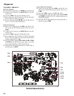
TX Gain Alignment 1 (SSB Hi Power)
r
Connect the 50
W
Dummy Load and Inline Wattmeter to the
ANT jack, then connect the AF Generator to the
MIC IN
jack
on the MIC Adapter Unit, and adjust the AF Generator to
1500 Hz, 8 mV.
r
Referring Table below, turn the transceiver to each channel
listed, and recall the computer to each parameter listed by
pressing the [
F7
] key. Press the [
F10
] key to activate the
SPOT-ADJ
mode, then key the transmitter and press the
[
S
HIFT
] + [
p
]/[
q
] keys for the required output.
r
Press the [
F2
] key to save the alignment value to the trans-
ceiver.
TX Gain Alignment 2 (SSB Low Power)
r
Connect the 50
W
Dummy Load and Inline Wattmeter to the
ANT jack, then connect the AF Generator to the
MIC IN
jack
on the MIC Adapter Unit, and adjust the AF Generator to
1500 Hz, 8 mV.
r
Referring Table below, turn the transceiver to each channel
listed, and recall the computer to each parameter listed by
pressing the [
F7
] key. Press the [
F10
] key to activate the
SPOT-ADJ
mode, then key the transmitter and enter the align-
ment values using the numeric keys for the required output.
r
Press the [
F2
] key to save the alignment value to the trans-
ceiver.
TX Gain Alignment 1 (AM Hi Power)
r
Connect the 50
W
Dummy Load and Inline Wattmeter to the
ANT jack.
r
Referring Table below, turn the transceiver to each channel
listed, and recall the computer to each parameter listed by
pressing the [
F7
] key. Press the [
F10
] key to activate the
SPOT-ADJ
mode, then key the transmitter with no micro-
phone input and press the [
S
HIFT
] + [
p
]/[
q
] keys for the
required output.
r
Press the [
F2
] key to save the alignment value to the trans-
ceiver.
TX Gain Alignment 2 (AM Lo Power)
r
Connect the 50
W
Dummy Load and Inline Wattmeter to the
ANT jack.
r
Referring Table below, turn the transceiver to each channel
listed, and recall the computer to each parameter listed by
pressing the [
F7
] key. Press the [
F10
] key to activate the
SPOT-ADJ
mode, then key the transmitter with no micro-
phone input and press the [
S
HIFT
] + [
p
]/[
q
] keys for the
required output.
r
Press the [
F2
] key to save the alignment value to the trans-
ceiver.
Alignment
Tune to
“
TXG A 1L
” channel
(3.50000 MHz, AM)
“
TXG A 2L
” channel
(5.00000 MHz, AM)
“
TXG A 3L
” channel
(7.50000 MHz, AM)
“
TXG A 4L
” channel
(11.00000 MHz, AM)
“
TXG A 5L
” channel
(16.50000 MHz, AM)
“
TXG S 6L
” channel
(25.00000 MHz, AM)
Recall Parameter
AM Tx Ga Lo (00-04)
AM Tx Ga Lo (04-06)
AM Tx Ga Lo (06-09)
AM Tx Ga Lo (09-13)
AM Tx Ga Lo (13-20)
AM Tx Ga Lo (20-30)
For
5 W
5 W
5 W
5 W
5 W
5 W
Tune to
“
TXG S 1H
” channel
(3.50000 MHz, USB)
“
TXG S 2H
” channel
(5.00000 MHz, USB)
“
TXG S 3H
” channel
(7.50000 MHz, USB)
“
TXG S 4H
” channel
(11.00000 MHz, USB)
“
TXG S 5H
” channel
(16.50000 MHz, USB)
“
TXG S 6H
” channel
(25.00000 MHz, USB)
Recall Parameter
SSB Tx Ga Hi (00-04)
SSB Tx Ga Hi (04-06)
SSB Tx Ga Hi (06-09)
SSB Tx Ga Hi (09-13)
SSB Tx Ga Hi (13-20)
SSB Tx Ga Hi (20-30)
For
20 W
20 W
20 W
20 W
20 W
20 W
Tune to
“
TXG S 1L
” channel
(3.50000 MHz, USB)
“
TXG S 2L
” channel
(5.00000 MHz, USB)
“
TXG S 3L
” channel
(7.50000 MHz, USB)
“
TXG S 4L
” channel
(11.00000 MHz, USB)
“
TXG S 5L
” channel
(16.50000 MHz, USB)
“
TXG S 6L
” channel
(25.00000 MHz, USB)
Recall Parameter
SSB Tx Ga Lo (00-04)
SSB Tx Ga Lo (04-06)
SSB Tx Ga Lo (06-09)
SSB Tx Ga Lo (09-13)
SSB Tx Ga Lo (13-20)
SSB Tx Ga Lo (20-30)
For
5 W
5 W
5 W
5 W
5 W
5 W
Tune to
“
TXG A 1H
” channel
(3.50000 MHz, AM)
“
TXG A 2H
” channel
(5.00000 MHz, AM)
“
TXG A 3H
” channel
(7.50000 MHz, AM)
“
TXG A 4H
” channel
(11.00000 MHz, AM)
“
TXG A 5H
” channel
(16.50000 MHz, AM)
“
TXG S 6H
” channel
(25.00000 MHz, AM)
Recall Parameter
AM Tx Ga Hi (00-04)
AM Tx Ga Hi (04-06)
AM Tx Ga Hi (06-09)
AM Tx Ga Hi (09-13)
AM Tx Ga Hi (13-20)
AM Tx Ga Hi (20-30)
For
20 W
20 W
20 W
20 W
20 W
20 W
Содержание VX-1210
Страница 16: ...16 Note ...
Страница 17: ...17 Block Diagram ...
Страница 18: ...18 Interconnection Diagram ...
Страница 28: ...28 Alignment Note ...
Страница 29: ...MAIN Unit 29 Circuit Diagram ...
Страница 30: ...30 MAIN Unit Note ...
Страница 44: ...44 Main Unit Note ...
Страница 45: ...CNTL Unit 45 Circuit Diagram ...
Страница 46: ...46 CNTL Unit Note ...
Страница 48: ...48 Side B 2SC2812 L6 Q2027 TC4S66F C9 Q2052 1SS319 A4 D2012 2 4 1 3 5 b a D c e d f g h CNTL Unit Parts Layout ...
Страница 56: ...56 CNTL Unit Note ...
Страница 57: ...57 PA Unit Circuit Diagram ...
Страница 58: ...58 PA Unit Note ...
Страница 60: ...60 Side B FMC5A C5 Q3001 3003 3005 MC2848 A6 D3003 3504 PA Unit Parts Layout 2 3 1 4 5 6 b a d c e f g h ...
Страница 65: ...65 Display Unit Circuit Diagram ...
Страница 70: ...70 Note ...
Страница 71: ...71 Tuner Unit ATU 1210 Option Circuit Diagram ...


