


12
Installation Manual Reprint
ATU-1210 I
NSTALLATION
M
ANUAL
Installation
r
Make sure that the transceiver is off. Remove the Battery
Pack, Microphone, and Antenna from the transceiver.
r
Referring to Figure 1, remove the two screws from the left
side of the transceiver.
r
Referring to Figure 2, remove the five screws from the rear
panel of the transceiver.
r
Draw off the rear panel and case from the transceiver body.
r
Referring to Figure 3, disconnect the coaxial cable from
J
3005
on the
PA U
NIT
.
r
Referring to Figure 4, disconnect the coaxial cable from
J
8101
on the
CONNECTION U
NIT
, then remove two screws affix-
ing the
CONNECTION U
NIT
and detach the
CONNECTION
U
NIT
from the transceiver.
r
Mount the
ATU-1210
Internal Antenna Tuner to the trans-
ceiver using the supplied five screws, then connect the co-
axial cable (which was disconnected from
J
8101
in the previ-
ous step) to
J
1001
on the
ATU-1210
(Figure 5).
Figure 1
Figure 2
Å
Å
J
3
0
0
5
PA UNIT
MAIN UNIT
Ÿ
Å
Å
Å
Å
Ç
Figure 3
r
Referring to Figures 5 and 6, route the coaxial cable from
JP
1002
on the
ATU-1210
as shown in the drawing, then con-
nect this cable to
J
3005
on the
PA U
NIT
.
r
Referring to Figures 5, 6, and 7, route the connection cable
from
JP
1001
on the
ATU-1210
as shown in the drawing,
then connect it to
J
2010
on the
CNTL U
NIT
.
r
Bundle the cables using the two supplied Cable Ties (Figure
6).
r
Replace the case and rear panel with its seven screws, using
care to avoid pinching or damaging the connecting wires and
wounding the
MIC
jack.
r
Connect the Battery Pack to the transceiver.
Содержание VX-1210
Страница 16: ...16 Note ...
Страница 17: ...17 Block Diagram ...
Страница 18: ...18 Interconnection Diagram ...
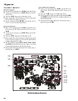
Страница 28: ...28 Alignment Note ...
Страница 29: ...MAIN Unit 29 Circuit Diagram ...
Страница 30: ...30 MAIN Unit Note ...
Страница 44: ...44 Main Unit Note ...
Страница 45: ...CNTL Unit 45 Circuit Diagram ...
Страница 46: ...46 CNTL Unit Note ...
Страница 48: ...48 Side B 2SC2812 L6 Q2027 TC4S66F C9 Q2052 1SS319 A4 D2012 2 4 1 3 5 b a D c e d f g h CNTL Unit Parts Layout ...
Страница 56: ...56 CNTL Unit Note ...
Страница 57: ...57 PA Unit Circuit Diagram ...
Страница 58: ...58 PA Unit Note ...
Страница 60: ...60 Side B FMC5A C5 Q3001 3003 3005 MC2848 A6 D3003 3504 PA Unit Parts Layout 2 3 1 4 5 6 b a d c e f g h ...
Страница 65: ...65 Display Unit Circuit Diagram ...
Страница 70: ...70 Note ...
Страница 71: ...71 Tuner Unit ATU 1210 Option Circuit Diagram ...