25
Alignment
Final Section Idling Current Alignment
r
Remove the Solder jumper from
JP3501
on the PA Unit,
and connect the DC Ammeter to
J3506
(pin 1: “–” lead, pin
2: “+” lead) on the PA Unit.
r
Select the “
TX IF
” channel (10.25000 MHz, USB).
r
Key the transmitter with no microphone input, adjust
VR3502
on the PA Unit for 100 mA ± 10 mA on the DC Ammeter.
r
Disconnect the DC Ammeter, and connect
JP3501
by sol-
der jumper.
CM Coupler Balance
r
Connect the 50
W
Dummy Load and Inline Wattmeter to the
ANT
jack, then connect the AF Generator to the
MIC IN
jack
on the MIC Adapter Unit, and adjust the AF Generator to
1500 Hz.
r
Connect the DC voltmeter to pin 3 of
JP3003
(“+” lead,
“–” lead: GND) on the CNTL Unit.
r
Select the “
CM BAL
” channel (29.9000 MHz, USB).
r
Turn the
HI/LOW
(Transmitter Power) Switch to the “up-
per” position.
r
Key the transmitter, then adjust the AF Generator output level
so that the Inline Wattmeter reading is approximately 20 Watts.
r
Now, adjust
TC3001
for minimum indication on the DC
voltmeter.
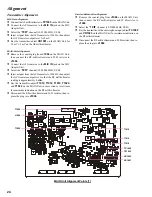
PA Unit Alignment Points
TC3001
VR3502
J3506
JP3003
JP3501
Содержание VX-1210
Страница 16: ...16 Note ...
Страница 17: ...17 Block Diagram ...
Страница 18: ...18 Interconnection Diagram ...
Страница 28: ...28 Alignment Note ...
Страница 29: ...MAIN Unit 29 Circuit Diagram ...
Страница 30: ...30 MAIN Unit Note ...
Страница 44: ...44 Main Unit Note ...
Страница 45: ...CNTL Unit 45 Circuit Diagram ...
Страница 46: ...46 CNTL Unit Note ...
Страница 48: ...48 Side B 2SC2812 L6 Q2027 TC4S66F C9 Q2052 1SS319 A4 D2012 2 4 1 3 5 b a D c e d f g h CNTL Unit Parts Layout ...
Страница 56: ...56 CNTL Unit Note ...
Страница 57: ...57 PA Unit Circuit Diagram ...
Страница 58: ...58 PA Unit Note ...
Страница 60: ...60 Side B FMC5A C5 Q3001 3003 3005 MC2848 A6 D3003 3504 PA Unit Parts Layout 2 3 1 4 5 6 b a d c e f g h ...
Страница 65: ...65 Display Unit Circuit Diagram ...
Страница 70: ...70 Note ...
Страница 71: ...71 Tuner Unit ATU 1210 Option Circuit Diagram ...


