22
Set up the test equipment as shown below, and apply 14.4V
DC power to the transceiver.
The VX-1210 must be programmed for use in the intended
system before alignment is attempted. The frequency and other
parameters are loaded from the file during the alignment pro-
cess.
In order to facilitate alignment over the complete switching
range of the equipment it is recommended that the channel data
first be uploaded and then stored to disk. Alignment Channel
data should then be downloaded. The original data can be re-
placed at the end of the alignment process.
Alignment
PLL Alignment
PLL Reference Frequency Alignment
r
Remove the coaxial plug from
J2009
on the CNTL Unit,
and connect the Frequency Counter to
J2009
.
r
Adjust
TC2001
on the CNTL Unit for 36.355 MHz ±10 Hz
on the frequency Counter.
VCO VCV Alignment
r
Connect the DC voltmeter to
TP2005
on the CNTL Unit,
and referring Table below, turn the transceiver to each chan-
nel listed. Then adjust the listed component for the required
voltage or confirm that the correct voltage is present.
Tune to
“
VCO 1 U
” channel
(8.99999 MHz, USB)
“
VCO 1 L
” channel
(0.50000 MHz, USB)
“
VCO 2 U
” channel
(18.9999 MHz, USB)
“
VCO 2 L
” channel
(9.00000 MHz, USB)
“
VCO 3 U
” channel
(30.00000 MHz, USB)
“
VCO 3 L
” channel
(19.00000 MHz, USB)
Adjust or Confirm
T2001
Confirm
T2002
Confirm
T2003
Confirm
For
6.0 V ± 0.1 V
1.3 ~ 2.3 V
6.0 V ± 0.1 V
1.0 ~ 2.0 V
6.0 V ± 0.1 V
1.0 ~ 2.0 V
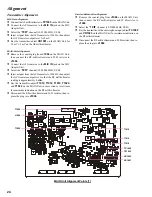
VX-1210 Alignment Setup
T2003
T2002
T2001
J2009
TC2001
TP2005
CNTL Unit Alignment Points
Содержание VX-1210
Страница 16: ...16 Note ...
Страница 17: ...17 Block Diagram ...
Страница 18: ...18 Interconnection Diagram ...
Страница 28: ...28 Alignment Note ...
Страница 29: ...MAIN Unit 29 Circuit Diagram ...
Страница 30: ...30 MAIN Unit Note ...
Страница 44: ...44 Main Unit Note ...
Страница 45: ...CNTL Unit 45 Circuit Diagram ...
Страница 46: ...46 CNTL Unit Note ...
Страница 48: ...48 Side B 2SC2812 L6 Q2027 TC4S66F C9 Q2052 1SS319 A4 D2012 2 4 1 3 5 b a D c e d f g h CNTL Unit Parts Layout ...
Страница 56: ...56 CNTL Unit Note ...
Страница 57: ...57 PA Unit Circuit Diagram ...
Страница 58: ...58 PA Unit Note ...
Страница 60: ...60 Side B FMC5A C5 Q3001 3003 3005 MC2848 A6 D3003 3504 PA Unit Parts Layout 2 3 1 4 5 6 b a d c e f g h ...
Страница 65: ...65 Display Unit Circuit Diagram ...
Страница 70: ...70 Note ...
Страница 71: ...71 Tuner Unit ATU 1210 Option Circuit Diagram ...


