


27
Tune to
“
TXP C 1H
” channel
(6.50000 MHz, CW)
“
TXP C 2H
” channel
(15.00000 MHz, CW)
“
TXP C 3H
” channel
(25.00000 MHz, CW)
Recall Parameter
SSB Po Hi (00-10)
SSB Po Hi (10-20)
SSB Po Hi (20-30)
For
20 W
20 W
20 W
Tune to
“
TXP C 1L
” channel
(6.50000 MHz, CW)
“
TXP C 2L
” channel
(15.00000 MHz, CW)
“
TXP C 3L
” channel
(25.00000 MHz, CW)
Recall Parameter
SSB Po Lo (00-10)
SSB Po Lo (10-20)
SSB Po Lo (20-30)
For
5 W
5 W
5 W
Tune to
“
TXP A 1H
” channel
(6.50000 MHz, AM)
“
TXP A 2H
” channel
(15.00000 MHz, AM)
“
TXP A 3H
” channel
(25.00000 MHz, AM)
Recall Parameter
AM Po Hi (00-10)
AM Po Hi (10-20)
AM Po Hi (20-30)
For
10 W
10 W
10 W
Tune to
“
TXP A 1L
” channel
(6.50000 MHz, AM)
“
TXP A 2L
” channel
(15.00000 MHz, AM)
“
TXP A 3L
” channel
(25.00000 MHz, AM)
Recall Parameter
AM Po L0 (00-10)
AM Po Lo (10-20)
AM Po Lo (20-30)
For
2.5 W
2.5 W
2.5 W
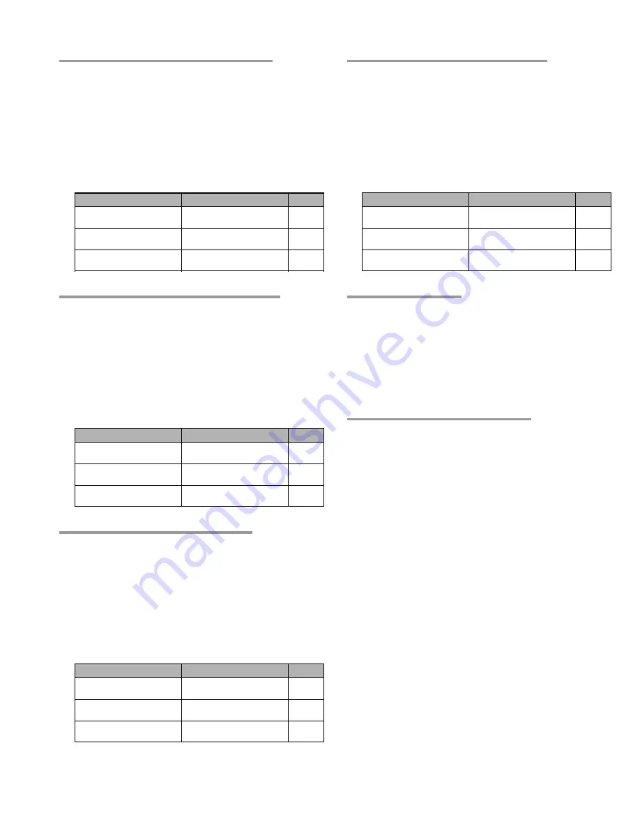
Alignment
Tx Output Power Alignment 1 (SSB/CW Hi Power)
r
Connect the 50
W
Dummy Load and Inline Wattmeter to the
ANT jack.
r
Referring Table below, turn the transceiver to each channel
listed, and recall the computer to each parameter listed by
pressing the [
F7
] key. Press the [
F10
] key to activate the
SPOT-ADJ
mode, then key the transmitter and press the
[
S
HIFT
] + [
p
]/[
q
] keys for the required output.
r
Press the [
F2
] key to save the alignment value to the trans-
ceiver.
Tx Output Power Alignment 2 (SSB/CW Low Power)
r
Connect the 50
W
Dummy Load and Inline Wattmeter to the
ANT jack.
r
Referring Table below, turn the transceiver to each channel
listed, and recall the computer to each parameter listed by
pressing the [
F7
] key. Press the [
F10
] key to activate the
SPOT-ADJ
mode, then key the transmitter and press the
[
S
HIFT
] + [
p
]/[
q
] keys for the required output.
r
Press the [
F2
] key to save the alignment value to the trans-
ceiver.
Tx Output Power Alignment 3 (AM Hi Power)
r
Connect the 50
W
Dummy Load and Inline Wattmeter to the
ANT jack.
r
Referring Table below, turn the transceiver to each channel
listed, and recall the computer to each parameter listed by
pressing the [
F7
] key. Press the [
F10
] key to activate the
SPOT-ADJ
mode, then key the transmitter and press the
[
S
HIFT
] + [
p
]/[
q
] keys for the required output.
r
Press the [
F2
] key to save the alignment value to the trans-
ceiver.
Tx Output Power Alignment 4 (AM Low Power)
r
Connect the 50
W
Dummy Load and Inline Wattmeter to the
ANT jack.
r
Referring Table below, turn the transceiver to each channel
listed, and recall the computer to each parameter listed by
pressing the [
F7
] key. Press the [
F10
] key to activate the
SPOT-ADJ
mode, then key the transmitter and press the
[
S
HIFT
] + [
p
]/[
q
] keys for the required output.
r
Press the [
F2
] key to save the alignment value to the trans-
ceiver.
Carrier Balance Alignment
r
With the 50 dB Attenuator (or 50
W
Dummy Load and Sam-
pling Coupler) and Spectrum Analyzer connected to the ANT
jack.
r
Select the “
TX IF
” channel (10.25000 MHz, USB).
r
Key the transmitter with no microphone input, adjust
TC1002
and
VR1003
on the MAIN Unit for minimum indication on
the Spectrum Analyzer.
Warning Indicator (Low Voltage) Alignment
r
Reduce the DC power to 13.8 volt.
r
Recall the [
Volt Warning 1
] parameter on the computer.
r
Press the [
F10
] key to activate the
SPOT-ADJ
mode, then
press the [
S
HIFT
] + [
p
]/[
q
] keys so that the front panel LED
will blink red when the [
F7
] key is pressed.
r
Reduce the DC power to 13.0 volt.
r
Recall the [
Volt Warning 2
] parameter on the computer.
r
Press the [
F10
] key to activate the
SPOT-ADJ
mode, then
press the [
S
HIFT
] + [
p
]/[
q
] keys so that the front panel LED
will glows red when the [
F7
] key is pressed.
Содержание VX-1210
Страница 16: ...16 Note ...
Страница 17: ...17 Block Diagram ...
Страница 18: ...18 Interconnection Diagram ...
Страница 28: ...28 Alignment Note ...
Страница 29: ...MAIN Unit 29 Circuit Diagram ...
Страница 30: ...30 MAIN Unit Note ...
Страница 44: ...44 Main Unit Note ...
Страница 45: ...CNTL Unit 45 Circuit Diagram ...
Страница 46: ...46 CNTL Unit Note ...
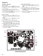
Страница 48: ...48 Side B 2SC2812 L6 Q2027 TC4S66F C9 Q2052 1SS319 A4 D2012 2 4 1 3 5 b a D c e d f g h CNTL Unit Parts Layout ...
Страница 56: ...56 CNTL Unit Note ...
Страница 57: ...57 PA Unit Circuit Diagram ...
Страница 58: ...58 PA Unit Note ...
Страница 60: ...60 Side B FMC5A C5 Q3001 3003 3005 MC2848 A6 D3003 3504 PA Unit Parts Layout 2 3 1 4 5 6 b a d c e f g h ...
Страница 65: ...65 Display Unit Circuit Diagram ...
Страница 70: ...70 Note ...
Страница 71: ...71 Tuner Unit ATU 1210 Option Circuit Diagram ...