


FPGA Registers
EPU-4562 Programmer’s Reference Manual
32
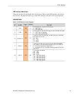
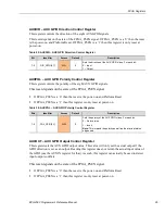
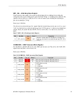
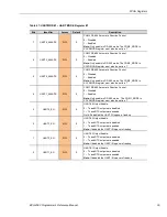
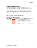
Table 40: FANCON – Fan Control Register
Bits
Identifier
Access
Default
Description
7
COM_MODE
R/W
1
Selects the COM Module fan control instead of the FPGA.
0 – FPGA controls fan on/off.
1 – COM Module controls fan on/off (or PWM if used) .
Note:
COM Module will only operate with 4-wire fans if using PWM
speed control. 3-wire fans are fine as long as it is just turned on or
off. PWM speed can be used with either type fan but the fan-tach
readings will not be stable on a 3-wire fan (but could possibly still
be used to monitor if the fan is stuck or not).
6-1
RESERVED
RO
0
Reserved – Writes are ignored. Reads always return 0
0
FAN_OFF
R/W
0
Fan Disable:
0 – Fan is On
1 – Fan is Off
Note
: On is the default in case there is no software turning it on.
This control only applies when COM_MODE is a ‘0’ (FPGA controls
fan on/off).
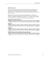
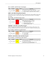
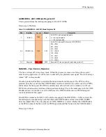
FANTACHLS,
FANTACHMS
–
FANTACH
S
TATUS
R
EGISTERS
The FPGA fan tach readings are always available and do not depend on either COM_MODE or
the FAN_OFF settings.
The number of fan tach output samples over a 1 second sampling period. The value is always
valid after the fan speed stabilizes and is updated every 1 sec (after a delay of 1 sec). Currently
only the lower 10-bits have a valid tach reading (i.e., the upper 6 bits will always be zero). The
fan tach count should never overflow in the 1 second period but it if does the value will “stick” at
0x03FF.
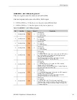
The design can handle up at least a 10,000 rpm fan with a fan tach output of up to 4 uniform
pulses per revolution. The duty cycle of the fan tach output pulse can be as low as 25% (typically
they are very close to 50%). The conversion to RPM is:
RPM = (FANTACH x 60) / PPR
Where,
FANTACH - the 16-bit register reading
PPR – fan tach pulses per revolution (typ either 1,2 or 4)
Reset type: Not Applicable