


FPGA Registers
EPU-4562 Programmer’s Reference Manual
22
Bit
Identifier
Access
Default
Description
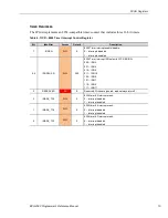
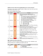
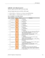
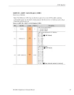
6-4
IRQSEL(2:0)
R/W
000
ADC ALARM Interrupt IRQ Select in LPC SERIRQ:
000 – IRQ3
001 – IRQ4
010 – IRQ5
011 – IRQ10
100 – IRQ6
101 – IRQ7
110 – IRQ9
111 – IRQ11
FYI – same values are other products.
3
ADC_RESET
R/W
0
ADS8668A ADC RESET
0 – deassert reset (normal operation)
1 – assert reset
NOTE: Always assert this for >400nsec since the part has some
strange modes for shorter resets. Regardless a standard Platform
reset will reset the A/D to a power-on reset state.
2
IN_ALARM
RO
N/A
Returns the ADS8668A ADC ALARM status value.
0 – ALARM is deasserted
1 – ALARM is asserted
1
ISTAT_ALARM
RO
N/A
ADC ALARM interrupt status. A read returns the interrupt status.
Writing a ‘1’ will clear the interrupt status. This bit is set to a ‘1’ on
a transition from low-to-high of the ADC ALARM signal (alarm
assertion)
0
IMASK_ALARM
RW
0
ADC ALARM Interrupt Mask:
0 – Interrupt disabled
1 – Interrupt enabled.
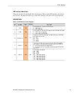
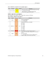
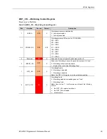
DIODIRx (x=1,2) – Digital I/O Direction Control Registers
These two registers control the directions of the 16 digital I/O signals.
This reset depends on the state of the FPGA_PSEN signal. If FPGA_PSEN is a ‘0’ then the reset
is the power-on and Platform Reset. If FPGA_PSEN is a ‘1’ then this register is only reset at
power-on.
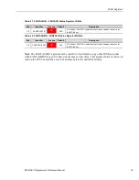
Table 16: DIODIR1 – Digital I/O 8-1 Direction Control Register
Bits
Identifier
Access
Default
Description
7-0
DIR_DIO[8:1]
R/W
0x00
Sets the DIOx direction. For each bit:
0 – Input
1 – Output
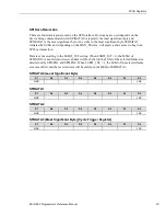
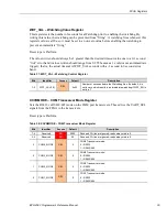
Table 17: DIODIR2 – Digital I/O 16-9 Direction Control Register
Bits
Identifier
Access
Default
Description
7-0
DIR_DIO[16:9]
R/W
0x00
Sets the DIOx direction. For each bit:
0 – Input
1 – Output