

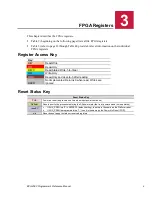


FPGA Registers
EPU-4562 Programmer’s Reference Manual
15
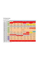
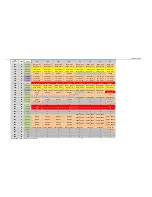
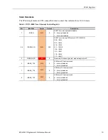
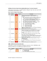
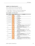
Table 10: MISCSR2 – Misc. Control Register #2
Bit
Identifier
Access
Default
Description
7
USB_HUBMODE
R/W
0
Determines whether the hub resets only once (to support wake-up from
sleep modes on USB ports) or resets every time it enters sleep modes
using the platform reset:
0 – USB Hub will be reset once at power on. Use USB_HUBDIS to
manually control the reset if necessary. This supports USB Wake-up
modes
1 – USB Hub will be reset by platform reset every time (will be reset
when entering all sleep modes). USB ports cannot be used to wake-up
6
W_DISABLE
R/W
0
Controls the W_DISABLE (Wireless Disable) signal going to the PCIe
Minicards (disables both minicards if asserted):
0 – W_DISABLE signal is not asserted (Enabled)
1 – W_DISABLE signal is asserted (Disabled)
Note:
There are other control sources that can be configured to control
this signal and if enabled the control becomes the “OR” of all sources
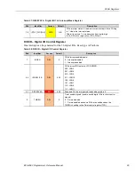
5
USB_HUBDIS
R/W
0
Control the reset on the USB2513B Hub (used for 3x Minicard USB
ports).
0 – USB2513 Hub is Enabled (reset released)
1 – USB2513 Hub is in Reset
Note:
FPGA was changed so that Platform reset drives this reset once
at power on.
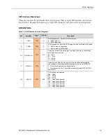
4
ETHOFF0
R/W
0
Disables Ethernet controller #0 (controls the ETH_OFF# input to the
I210-IT):
0 – Ethernet controller is enabled (On)
1 – Ethernet controller is disabled (Off)
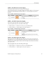
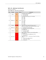
3
USB2_OC2
RO
N/A
Overcurrent Status from the USB 2.0 port 2,3 VBUS power switches.
This signal also passed to the fourth USB_6_7_OC# input on the COM
Express connector.
0 – VBUS power switch is not in overcurrent (either OK or disabled)
1 – VBUS power switch is in overcurrent and is now off.
Note:
The power switches latch-off in overcurrent and can only be re-
enabled by a power-cycle or by setting this bit to a ‘1’, wait >1msec and
then a ‘0’
2
USB2_OC1
RO
N/A
Overcurrent Status from the USB 2.0 port 0,1 VBUS power switches.
This signal also passed to the third USB_4_5_OC# input on the COM
Express connector.
0 – VBUS power switch is not in overcurrent (either OK or disabled)
1 – VBUS power switch is in overcurrent and is now off.
Note:
The power switches latch-off in overcurrent and can only be re-
enabled by a power-cycle or by setting this bit to a ‘1’, wait >1msec and
then a ‘0’
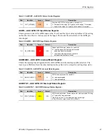
1
USB2_DIS2
R/W
0
Disable control for the paddleboard USB 2.0 ports 2,3 VBUS power
switches (there are two power-switches but they have a common power
enable and overcurrent status)
0 – VBUS power switches are enabled
1 – VBUS power switched are disabled.
Note:
The power switches latch-off in overcurrent and can only be re-
enabled by a power-cycle or by setting this bit to a ‘1’, wait >1msec and
then a ‘0’