


3 Wiring and Connections
51 SD780 Series Servo Technical Manual
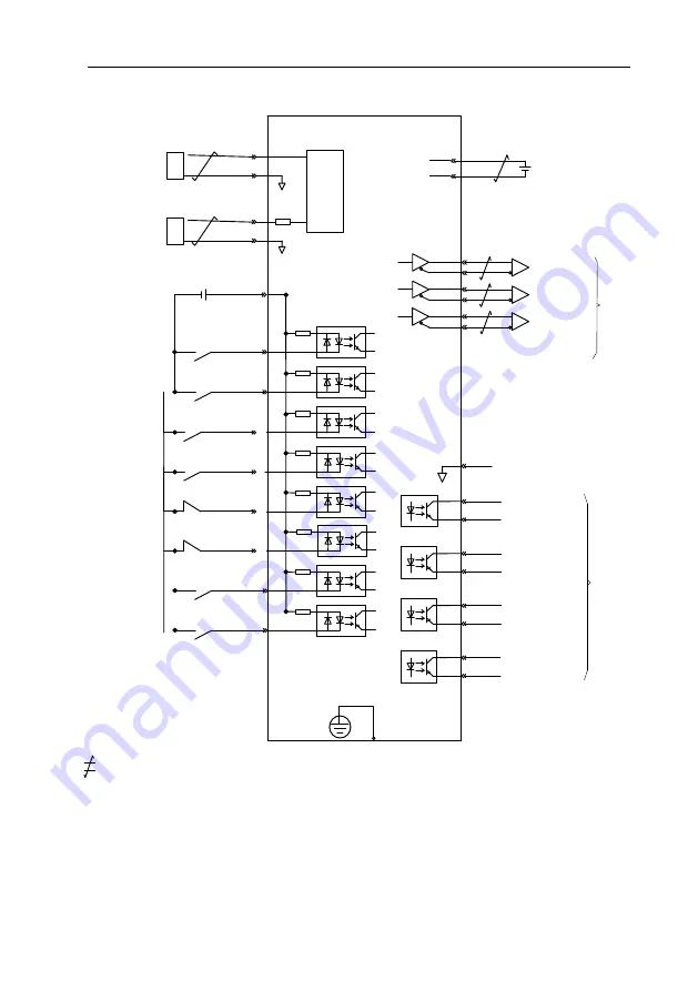
3.13 Torque Control Wiring Diagram
COIN+
COIN
-
S
-
RDY+
S
-
RDY
-
ALM+
ALM
-
SG
PAO
/PAO
PBO
/PBO
PCO
/PCO
A phase of encoder
pulse division output
B phase of encoder
pulse division output
C phase of encoder
pulse division output
Signal ground
Position finished
(ON while finished)
Servo ready output (ON)
while receivable /SON)
Servo alarm output
OFF while alarm
CN1
Linear
receiver:
SN75ALS175
or
MC3486
of
T.I. company
Connector shell
FG Shields are connected to connector shell
Frame grounded
Max
voltage of
optocoupler
output
:
DC 30V
Max
current:
DC 50mA
33
35
36
19
20
34
1
25
26
27
28
29
30
31
32
5
9
10
6
V
-
REF
SG
SG
T
-
REF
Speed command input
(
Max input voltage:
± 10V
)
D/
A
D/
A
A/
D
Torque command input
(
Max input voltage:
± 10V
)
Battery of absolute
encoder
3.2V
~
4.5V
*
3
21
22
BAT(+)
BAT(
-
)
*
2
/S
-
ON
/P
-
CON
/P
-
OT
/N
-
OT
/ALM
-
RST
/TLC
Servo ON Input
(Servo ON while signal ON)
P operation command input
(P operates while ON)
Forbid FWD driving input
(Forbidden while OFF)
Alarm reset input
(Reset while on)
Torque limit selection
(
According to torque limiting
mode
)
Forbid REV driving input
(Forbidden while OFF)
40
41
42
43
44
45
+24V
47
+24VIN
39
/ZCLAMP
38
/C
-
SEL
Zero
-
position fixation input
(Valid while ON)
Control mode switch input
(valid while ON)
*2. DC24V
power should be prepared by user. And double insulation or reinforced insulation equipments should be used for DC24V power.
*
3
.
Connected while using absolute encoder. But never connect backup battery while using encoder cables with battery unit.
*4.
Output signal should be received by linear receiver.
Note: While using 24V braker,DC24V power should be separated from the power for input and output signal (CN1). Please prepare
other power individually,
otherwise, there may be misoperation of input and output signal while power on.
*1.
is the twisted shields.
/V
-
CMP+
/V
-
CMP
-
The speed is consistent
(ON while consistent)


