AC70 VC CONTROL FREQUENCY INVERTER MANUAL
FUNCTION PARAMETER DETAILED SPECIFICATION
95
LED ten digit: UP and DW terminal control starting frequency setting
0: Runs with UP/DW terminal adjusting without save the frequency record after power loss.
1: UP/DW terminal adjusting, save the frequency record after power off stop. Inverter will run to last stop moment
frequency and then perform UP/DW adjusting. (Refer to
[F-70]
to Check or modify last stop moment frequency).
2. Runs to preset frequency
[F-70]
first, and then execute UP/DW adjusting.
LED hundred digit: STOP/RESE of keypad effective range selection.
0: STOP/RESE key valid only when under keypad control
1: STOP/RESE key valid under any run command source. This function is suitable for using emergency stop in
NOT keypad control mode.
Note: If selects to STOP/RESE key valid under any run command source, pressing the stop key of keypad,
inverter will be located in stop lock status when in terminal control or RS485 control mode. If want to using
terminal or Rs485 running control channel command to restart inverter running, you must sent stop
command by given channel to unlock stop status first. Frequency inverter enable to restart after stop
status unlocking.
LED thousand digit: Terminal running mode selection after fault reset
0: Start inverter running directly after power on in terminal control mode
1: Stop first and then start in terminal control mode
Note: When fault occurs of inverter, reset valid signal can be sent by the all 3 running control command. If
the frequency inverter adopts the terminal control mode, after frequency inverter reset by receiving
terminal or the other two channels’ reset signal, this parameter can be used to select whether to carry on
the terminal running command.
F-08
Terminal running control mode
Range:0000-0005
Default: 0000
LED unit digit: Terminal control mode selection
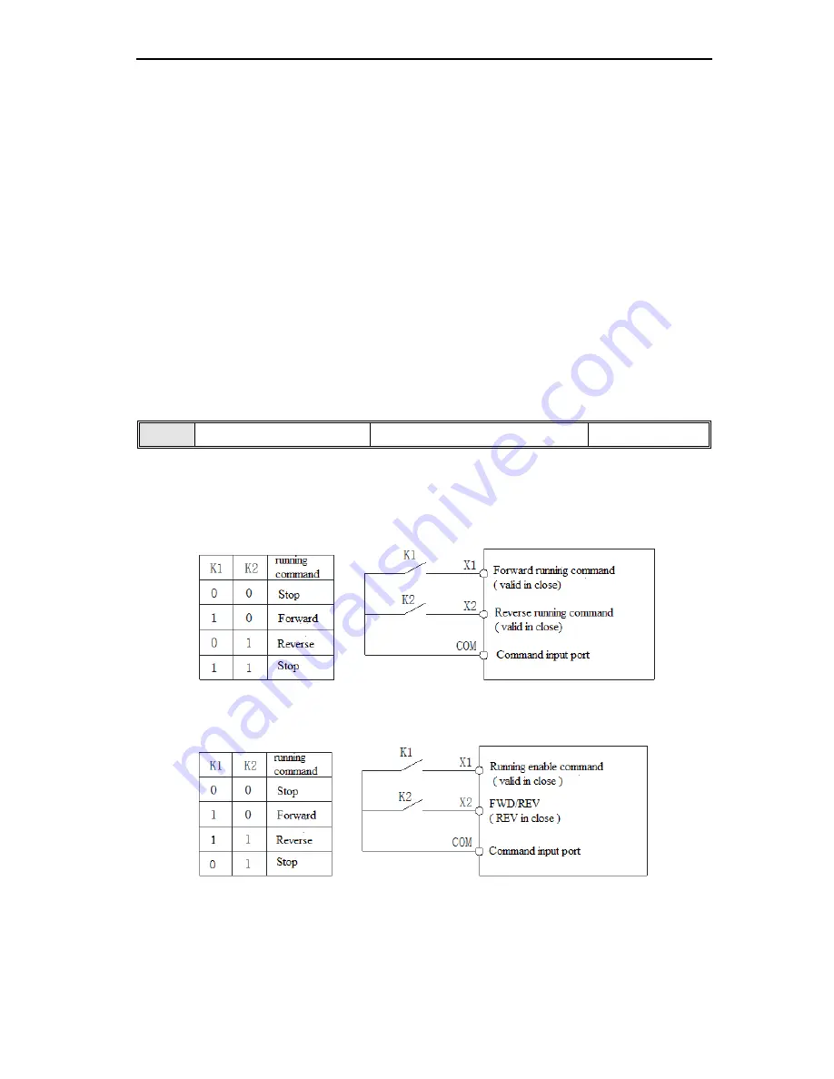
0: Standard running control mode
Running and direction are bonded together. This 2 wire control mode is
most commonly using. Uses X1 (forward running) and X2 (reverse running) terminals command to determine the
Forward /Reverse running of motor. Refer to below fig.
1: Two wire running control mode
Running and direction are separated. Uses the forward running terminal X1
(forward running) to determine running control, reverse running terminal X2 (reverse running) to determine direction
control. Refer to below fig.
2. Three wire control mode 1
Three wire control terminal (Xi) is used for stop running terminal. Running
command determined by forward running terminal X1 (forward running), direction determined by reverse running
terminal X2 ( reverse running). 3 wire running control terminal Xi is used for enable input.


