


Electric Force (EFM) Imaging
Electric Field Gradient Detection—Procedures
Rev. B
MultiMode SPM Instruction Manual
259
•
Adjust the sample or tip voltage to con
fi
rm that contrast is due to electrical force
gradients. On very rough samples, contrast in
LiftMode
images may be from air
damping between the tip and surface. It is often useful to look at the phase data in
Scope
Mode
while adjusting the tip or sample voltage up and down. Contrast due to electrical
force gradients should increase or decrease as the tip-sample voltage is changed.
•
For more quantitative results, switch the to the frequency
Data Type
for Channel 1. This
technique provides a direct measure of the change in resonant frequency felt by the
cantilever. It may be necessary to optimize the FM (frequency modulation) gain to
properly track the shifts in resonant frequency. This is described in detail in
of the appropriate product instruction manual.
14.4.2 Amplitude Detection
With
Basic Extender Module
To set up for
Amplitude Detection
fi
eld gradient imaging on systems
with
the Extender module
installed, follow the instructions in
, with the exception that the
Channel 1
Data Type
should be set to
Amplitude
.)
Without
Basic Extender Module
Note:
This imaging method, although described here, is not recommended
without
the Basic Extender Module due to the presence of artifacts.
Amplitude Detection
, unlike
Phase Detection
, is available
with
or
without
the optional Basic
Extender Module. This section describes the differences in software set up and imaging for EFM
systems
without
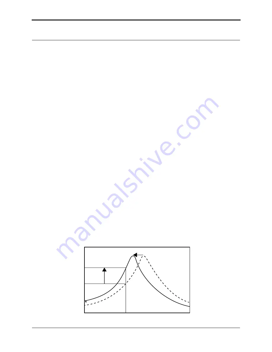
the Extender module. When EFM imaging
without
the Extender module, changes
in the cantilever amplitude provide an
indirect
measure of shifts in the cantilever resonance
frequency as shown in
Figure 14.4d
Shift in amplitude at
fi
xed
Drive Frequency
(Basic Extender Module
not
installed).
Drive Frequency
Amplitude
∆
F
0


