background image

PAGE:

REVISION:

DATE:

VAN'S AIRCRAFT, INC.

42PiS-01

RV-12iS

0

01/19/19

PARTICIPANTS:

DATE OF COMPLETION:

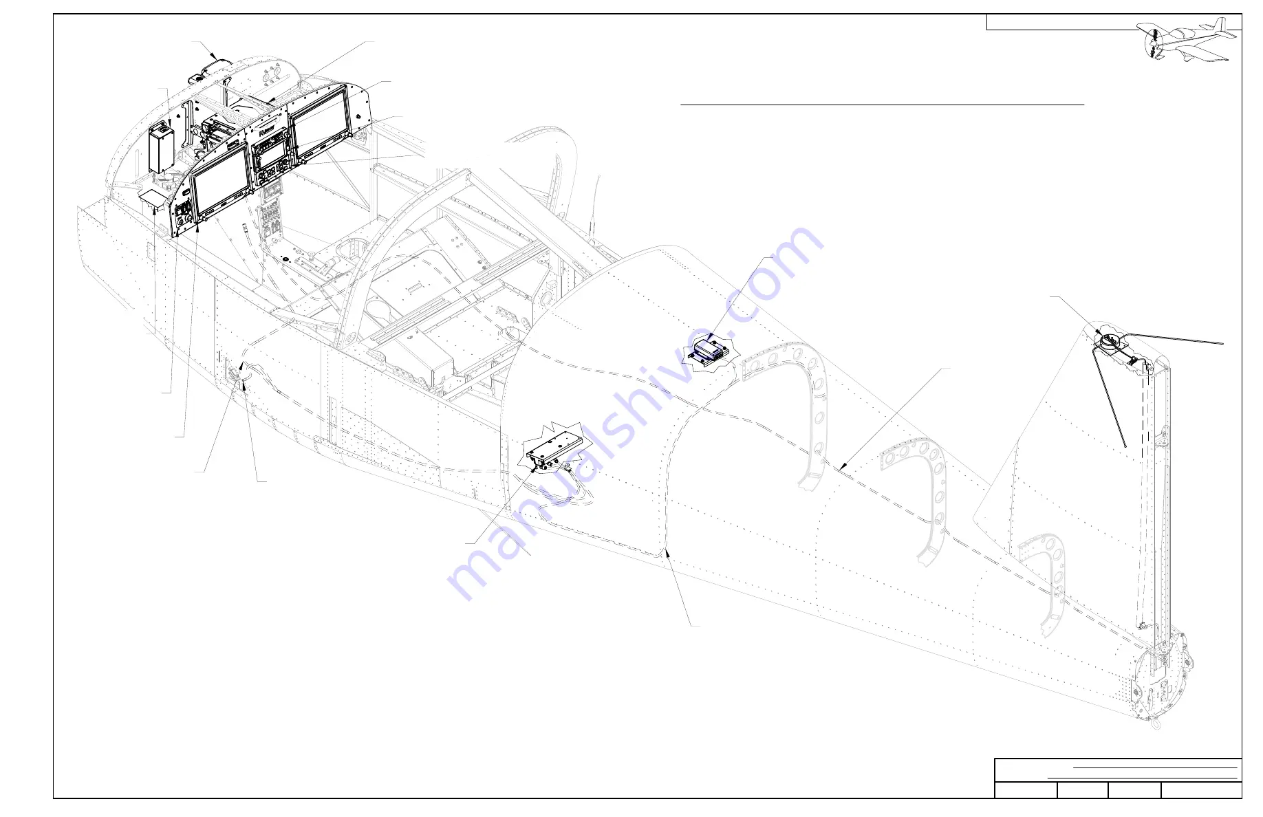
(AV-532L CABLE)

AV-532L

VOR/LOC/GS ANTENNA

GMU 11
GARMIN
MAGNETOMETER

GSU 25

GARMIN AIR DATA

ATTITUDE HEADING

REFERENCE SYSTEM

GMA 245
GARMIN AUDIO PANEL

GTN 650
GARMIN GPS/NAV/COM

GEA 24

GARMIN ENGINE

INDICATION

SYSTEM

GA 36 OR GA 37

GARMIN GPS ANTENNA

F-00214

GARMIN AFT PITOT LINE

F-00212
GARMIN AOA LINE

F-00216
GARMIN STATIC LINE

2X GDU 460

G3X TOUCH

FLIGHT DISPLAY

AV-60007

IGNITION

MODULE

GTX 35R
GARMIN TRANSPONDER

SECTION 42PiS:

GARMIN G3X

NAV/COM SYSTEM

GMC 307
GARMIN CONTROL PANEL

GAD 29

GARMIN DATA

INTERFACE

ADAPTER

Содержание G3X

Страница 1: ...NCE SYSTEM GMA 245 GARMIN AUDIO PANEL GTN 650 GARMIN GPS NAV COM GEA 24 GARMIN ENGINE INDICATION SYSTEM GA 36 OR GA 37 GARMIN GPS ANTENNA F 00214 GARMIN AFT PITOT LINE F 00212 GARMIN AOA LINE F 00216...

Страница 2: ...de all 40 holes just match drilled into the VS 1213 for an AN426AD3 rivet See Figure 2 Step 5 Final drill 27 then machine countersink all 30 holes in the VS 1213 See Figure 2 Step 6 Rivet the nutplate...

Страница 3: ...own in Figure 2 Step 7 Rivet the nutplates to the bottom of the F 00203 as shown in Figure 2 Step 8 Using the marks made in Step 3 as a starting point trim away the inside edge of the lightening hole...

Страница 4: ...tical height of the AV 532L Antenna element above the top edge of the VS 1201 as shown in Figure 1 and record the value Remove the AV 532L from the V Stab Assembly Step 7 Temporarily install the VS 12...

Страница 5: ...the F 00204 through the aft most set of lightening holes in the ribs of the V Stab Assembly See Figure 2 Step 4 Secure the F 00204 to the ES 00301 on the top of the V Stab Assembly The F 00204 should...

Страница 6: ...Step 2 Use a step drill to enlarge the 30 hole in the F 1278 to 5 8 Step 3 Install the snap bushing into the F 1278 as shown in Figure 1 Step 4 Cut strips of MS21266 Grommet to the length shown in Fig...

Страница 7: ...dge of of the F 1279 R Upper Right Skin stiffener and is clear of all control cables Step 2 Route the AV 532L cable through the snap bushing in the F 1278 Step 3 With the AV 532L cable extending outsi...

Страница 8: ...01207C L route the AV 532L cable forward through the airframe and up through the wire pass through hole in the F 01202B 1 as shown in Figure 1 Step 3 Install the F 1257Bs onto the F 1281 R stiffener...

Страница 9: ...be used to pull the AV 532L cable up through the F 00204 if necessary Step 2 Connect the ring terminals on the end of the AV 532L cable onto the studs of the AV 532L antenna with the included fastene...

Страница 10: ...tailcone skins as shown in Figure 2 Ensure the GMU 11 connector is facing aft Step 3 Connect the 9 pin d sub connector labeled MAGNETOMETER from the WH 00136 to the GMU 11 F 000142 FIGURE 1 GMU 11 IN...

Страница 11: ...n Figure 1 This will form the ADAHRS Baggage Floor Assembly FIGURE 1 ADAHRS BAGGAGE FLOOR ASSEMBLY FIGURE 2 INSTALLING THE ADAHRS Step 4 Bolt the GSU 25 to the ADAHRS Baggage Floor Assembly as shown i...

Страница 12: ...bricate the F 00214 Garmin Aft Pitot line Step 8 Route one end of the F 00214 through the lightening hole in the F 01207B 1 as shown in Figure 2 then insert the end of the F 00214 into the FLF 00007 i...

Страница 13: ...ong its length and does not interfere or chafe against fuel lines brake lines engine and fuel control cables etc The F 00214 will be connected to the FF 1216 Pitot Line later in this section Step 3 Lo...

Страница 14: ...ole noted in Figure 2 into the F 00063 This hole is not used for the G3X Touch installation NOTE The two upper screw holes in the F 00063 will make notches in the F 01202B 1 flange See Figures 2 and 3...

Страница 15: ...00063 R MS21051 L06 2X AN426AD3 3 5 MS21051 L06 2X AN426AD3 4 6X K1000 06 2X AN426AD3 4 AN426AD3 3 5 Step 1 Rivet the F 00063 L and nutplates to the forward side of the F 01202B 1 Panel Base flange a...

Страница 16: ...rsink the nutplate rivet holes in the F 00054 1 L 1 R then install the nutplates as shown in Figure 3 6X MS21055 L06 2X AN426AD3 3 5 8X K1000 06 2X AN426AD3 3 5 F 00054 1 R F 00054 1 L REMOVE HATCHED...

Страница 17: ...ep 4 Cleco the F 00132 R to the F 01201A 1 as shown in Figure 1 Step 5 Match drill 30 the holes in the F 00132 R and the F 00132 L Drill Guide as shown in Figure 1 Step 6 Match drill 11 the holes in t...

Страница 18: ...oute the WH 00136 main wire harness branches through the slotted holes in the F 00130 L R Step 6 Split the snap bushings then place the snap bushings over each branch of the WH 00136 Secure the snap b...

Страница 19: ...l the P1001 P1003 and P1004 connectors part of the WH 00136 on to the backplate Connect the COM NAV and GPS Coaxial cables part of the WH 00136 to the respective connectors on the backplate Step 2 Ins...

Страница 20: ...ion Manual and Figure 1 Step 2 Install the Garmin GMA 245 backplate in the GMA245 mounting rack as shown in the GMA 245 Installation Manual and Figure 1 Step 3 Fasten the GMA 245 mounting rack to the...

Страница 21: ...apter Plate onto the F 01201A 1 Firewall Top with the hardware called out in Figure 1 Step 3 Apply a thin coating of fuel tank sealant over the heads of the screws on the forward side of the firewall...

Страница 22: ...port labled GPS on the GA 36 Step 4 Secure the GA 26C Garmin GPS Antenna to the F 00196 with the included fasteners as shown in Figure 2 Step 5 XM Only Connect the TNC Connector labeled XM from the WH...

Страница 23: ...3 Connect the d sub connector labeled XPNDR and the BNC connector labeled XPNDR from the WH 00136 to the GTX 35R Backplate Assembly as described in the GTX 35R Installation Manual See the detail view...

Страница 24: ...5 pin d sub connector labeled BATT from the WH 00136 to the IBBS 12V 3AH See Figure 1 Step 3 Gather the WH 00136 near the inboard aft corner of the ES CPU Fan using the clamp as shown and install the...

Страница 25: ...Figure 3 Step 10 Repeat and mirror Steps 1 through 9 with the F 00065S for the right side of the aircraft F 1202D L MS21051 L06 3X MATCH DRILL 40 CENTER NUTPLATES ON FLANGE 4X AN426AD3 3 5 LOCATE NUTP...

Страница 26: ...ure the switch orientation matches the detail view in Figure 1 Step 3 Purchase then install the internal battery in the E 04 5 Cockpit Remote Refer to the instructions provided with the AV E 04 ACK 40...

Страница 27: ...the F 00043S F 00129 and F 00065S with screws Step 2 Locate the co pilot push to talk switch labeled PTT from the WH 00136 Discard the hex nut and star washer included with the switch then attach the...

Страница 28: ...6 to the AV 60007 Step 2 Connect the three ES 421 0108 connectors from the WH 00136 to the ES SW K1 AABAAAAA as shown Step 3 Connect the 50 pin d sub connector labeled PFD from the WH 00136 to the GDU...

Страница 29: ...README file NOTE Functional checks of the system will be conducted as a part of the Production Acceptance Procedures NOTE Completion of the avionics installation is a good time to start gathering the...

Страница 30: ...VAN S AIRCRAFT INC PAGE REVISION DATE 01 19 19 0 RV 12iS 42PiS 30 THIS PAGE INTENTIONALLY LEFT BLANK...

Отзывы: