background image

Pag 40 


< PICTURE 5.36 >


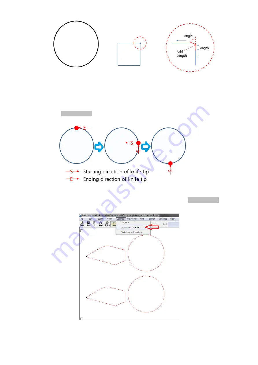
Adjustment Starting Point 
 

You can select starting point of cutting in each object. Adjust of starting point is important for some cases, 
because the direction of knife tip on starting point of new object is depending on ending point of the 
previous object. See <Picture 5.37> to understand better. 


< PICTURE 5.37 >


Select Setting menu and select ‘Drop point knife set’ from the menu, as shown in <Picture 5.38>  
This will not be activated if you do not have cutting lines assigned as ‘Ncut’. 


< PICTURE 5.38 >


Содержание DUOBLADE F

Страница 1: ...Pag 1 DUOBLADE F Digital Die Cutting System User Guide v 2 1 1 Please read this manual carefully before using the device Valloy Incorporation 2018 June 1st ...

Страница 2: ...ndisclosure and proprietary information agreements currently in effect with your organization Copies of this document any portion of this document or attachments may not be transmitted or disclosed to any third party without the prior written permission of VALLOY Inc 2018 VALLOY Inc All content is the confidential property of or licensed to VALLOY Inc VALLOY we or us and is protected under Rep of ...

Страница 3: ...hapter 4 Preparation 14 4 1 Mark Sensor Setting 12 4 2 Cutting Head Installation 13 4 3 Material Preparation 16 4 4 Die Cutting Preparation 16 Chapter 5 System Operation Instructions 17 5 1 Panel Operation Instructions 17 5 2 Software Installation 23 5 3 File Design 24 5 4 Converting Cutting File Format AI2PLT 32 5 5 How To Connect The Machine With PC 33 5 6 DUO BLADE Software Operation 35 Chapter...

Страница 4: ...when handling the installation 1 Make sure the ground strength is sufficient to support the machine 2 Lifting of the machine by lifter should be done by professional operator 3 When lifting the machine nobody is allowed to be under or near the machine 4 A safety Helmet is required during handling installation or cleaning 5 If it is necessary to reach upper parts on the machine use a safe and sturd...

Страница 5: ...rally one operator is required for this machine If more than one operator is working on the machine there should be good communication between operators 5 Precautions for maintenance Always turn off the power supply during maintenance Safety precautions during maintenance are as follows 1 Turn off the main power before inspection or maintenance 2 Maintenance or inspection should be carried out by ...

Страница 6: ...which may cause personal injury Be away from rolling parts like rollers or belts of running machine which may cause personal injury Do not touch the machine by hands during machine is running Be sure to connect the ground wire at installation of the machine Be cautious not to be electrically shocked ...

Страница 7: ...ill damage the power supply resulting in electric shock or fire If you do not use the machine for a long time please unplug the power cable from the wall socket Otherwise it may cause a fire When operating hands must not be placed near from the moving or rolling object of the machine This will cause harm When unplugging the power cable from the wall socket you should pull the plug should not pull ...

Страница 8: ...ing transported raise the floor mat first then you can drag or push the machine on its wheels When you encounter uneven ground you need to use a forklift or hydraulic vehicle to carry the machine 2 5 Space requirements Length 2 meters Width 1 5 meters Height 2 meters 2 6 Electrical specifications The voltage used by this station is single phase 220V 50 60Hz Use proper transformer for 110V power 2 ...

Страница 9: ...Blade F Digital die cutting machine DB340F Maximum paper width 340mm Maximum paper length 570mm Maximum label width 340mm Minimum label width 10mm Maximum label length 500mm Minimum label length 10mm Cutting speed 3 m s according to die cut content No of Die cutting head 2 ea Die cutting technology Carbide rotary cutter Die cutting accuracy 0 1MM repeat Die positioning Manual black mark single or ...

Страница 10: ...Pag 10 3 3 DuoBlade F DB340F Digital Die Cuter Parts Description Structural components schematic PICTURE 3 1 PICTURE 3 2 1 2 3 4 5 6 7 9 10 11 12 14 8 13 ...

Страница 11: ... stop 2 switch 3 control panel 4 Pressing lever 5 Feed elevator 6 Cardboard 7 Suction suction module 8 Double knife assembly slider assembly 9 Data transmission port 10 Main power switch 11 main power port 12 Casters 13 Paper bucket 14 Marking sensor ...

Страница 12: ...cutting Move the mark sensor and place the sensor s light spot at the center of the black mark Usually we use 4 mm x 4 mm square black marks If you are using dark colored marks on a light background media set the D L switch to L light position Move the white background into the sensor s focus Rotate the adjusting knob to starting position of the right limit position Turn the adjusting knob to the ...

Страница 13: ...on the other direction 4 2 Cutting head installation There are many kinds of cutting blades Select the cutting blade that best suits the media to be cut Cutting blade Part number Diameter and offset Compatible knife Holder Applications and features VD 09U ø0 9 mm 0 45 VD340 09U Cut color stickers standard blade Suitable for cutting 0 25 mm thick media Cutting length about 4000 m VD 15U ø1 5 mm 0 7...

Страница 14: ...de from the holder cap Step 4 Insert the new blade into the hole in the holder cap Step 5 Insert the blade into the holder cap and tighten the holder cap 3 Adjust the blade length If the blade protrudes longer than the thickness of the media to be cut it can damage the cutting pad Be sure to adjust the blade length correctly Step 1 Rotate the blade length adjustment knob to adjust the blade length...

Страница 15: ... to or slightly longer than t l must not exceed the total thickness of the face paper and its base paper If you cannot accurately determine the thickness of the tissue increase it little by little to adjust the knife The length of the blade until the blade leaves only traces on the base paper after cutting PICTURE 4 8 Step 4 Loosen the pen holder screw and attach the cutting knife After the cuttin...

Страница 16: ...If you are using double knives at the same time you need to adjust the distance between the heads on the control panel After sending a file from a computer or reading a file from a USB flash drive the lifting platform of the die cutting machine will rise till top material s touching the upper limit sensor The suction belt delivers the top sheet of material to the cutting platform automatically 4 4...

Страница 17: ...ble Mark means it senses left up mark and left bottom mark together for better accuracy Settings Moves to Settings window Ref No 2 Test Additional functions like Manual Setting Ref No 7 D Head 30 110 The distance between the two knives when using dual knife cutting If you want to set over 110 move 2nd holder to another side of head Distance of two hole is 80mm Reset It is recommended to use this b...

Страница 18: ...0 300 X offset distance of the knife relative to the origin in unit of 0 01 millimeters Y Cut Ad 300 300 Y offset distance of the knife relative to the origin in unit of 0 01 millimeters 4 Cut speed 1 1600 Change cutting speed in mm s unit when moving on straight line Higher value faster speed Max value is 1600 mm s Cut Acc 1 300 Change acceleration level of cutting speed Higher value faster accel...

Страница 19: ...glish Select GUI language Mark length 0 100 Unit is mm set mark length 4mm as default Mark width 0 100 Unit is mm set mark length 4mm as default Find Input B W Select Black or White set track sensor s mark color Send Input B W Select Black or White set feeder sensor s mark color X Length 0 10000 X direction cutting range in mm unit Use higher head pressure for larger area to cut Y Length 0 10000 X...

Страница 20: ...e unit gf cm2 Blade P 2 400 1000 The larger the setting the greater the knife pressure unit gf cm2 HS LS High speed low speed Speed of heads when moving manually e g finding marks ARROW BUTTONS up down left right Move the head or sensor by using the arrow keys Old T Pre factory equipment test mode users do not need to operate Back Return to previous menu ...

Страница 21: ... for better understanding Verticality angle X vert and Y vert parameters can change angles in X and Y direction as below picture To understand more about Verticality it is related with twisting the image in X and Y direction separately Image angle can be changed by adjusting X Vert and Y Vert value together Below picture is showing how X Vert and Y Vert work separately Scale X Scale and Y Scale ad...

Страница 22: ...trol Speed and acceleration can be very sophisticatedly controlled in Duo Blade F These parameters are dependent to the shape and complexity of cutting design itself Acceleration means how fast to each to the target speed from starting point or hot fast to stop cutting at end point Speed and acceleration can be differently setup for straight lines and curves Be sure to use less values of Bend Spee...

Страница 23: ...B dongle Lock key Below is common order to preparing cutting file 1 Design your label with black Mark and cutting line in illustrator 2 Making cutting file and save as ai format 3 Convert ai to plt in our AI2PLT software 4 Run DB 320S cutting software and open plt file 5 Click cutting line and start Please double click VALLOY DuoBlade Die Cut Setup exe in the CD CD and USB lock key is delivered by...

Страница 24: ...utting contours for cutting Make contours invisible during printing and delete printable designs during exporting of cutting file Corel Draw In case of Corel Draw it allows saving as HPGL1 PLT file Export the die cut file to PLT format The plotting unit is 1013 and the curve resolution is 0 Detailed explanation about file preparation and designing will be followed in case of using Adobe Illustrato...

Страница 25: ...arks side by side with the design Black marks need to be min 1mm x 1mm size but we recommend 4mm x 4mm size in general The gap between object and black marks needs to be at least 1mm in X and Y direction like Picture 5 3 PICTURE 5 3 PICTURE 5 4 Sequence of black marks in the design itself is also important We advise put right mark first and second mark later to measure the first black mark that is...

Страница 26: ... Refer to Picture 5 5 It is very important to set cutting area on the machine If you set wrong position cutting head will not be able to correct cutting position PICTURE 5 5 Black Mark Making Size We recommend 4 mm X 4 mm size PICTURE 5 6 Also please meet same Black Mark size values in the machine like below PICTURE 5 7 Color and out line ...

Страница 27: ...black Mark please design 2 black marks in the design for future use Caution Black marks needs to be located in the first layers bottom position of layer sequence Cutting software doesn t accept the black mark in other position like PICTURE 5 10 PICTURE 5 10 When you use two black Mark it should be located on the first and second layer order position Refer to PICTURE 5 11 ...

Страница 28: ...uence of black marks It is important to make the cutting head movement path as simple as possible to reduce the inaccuracy and maximize the cutting speed For example in below Picture 5 13 the illustrate sequence of objects will optimize and simplify the path of cutting head movement Caution Please arrange layer order as like a picture If you want to change cutting order you can re arrange 3 4 5 6 ...

Страница 29: ...tween labels have no limitation but recommended gap is 3mm 5mm Too narrow gap will make problems during matrix removal weak matrix can tear easily PICTURE 5 14 It is also possible to put multiple rows of same images in a single design like Picture 5 15 Next black mark will not be sensed until one job is finished It gives the same effect with using Track J refer to Table on page 17 as more than 2 t...

Страница 30: ...E 5 15 Do not use any Grouping Compound Path or Clipping Mask function in illustrator These functions will cause unknown bugs on AI2PLT converting software Use Join to combine paths of different objects PICTURE 5 16 ...

Страница 31: ...7 How to Save on illustrator If you make or revise cutting file successfully in illustrator then please save as ai file In this time please save the file without Use Compression option Illustrator Compression makes program crashes with AI2PLT If you forget to remove this option and save the file it will not be converted in AI2PLT PICTURE 5 18 ...

Страница 32: ...un AI2PLT software B Open cutting file which you saved as ai format C Click Convert PLT D PLT file will be generated in the same folder 2 Enable Spool function A Run AI2PLT software B Click Enable Spool check box C When you copy your ai file to assigned folder the software will generate new PLT file to assigned folder and move original file to assigned folder automatically You can find default fol...

Страница 33: ...ou don t know the IP address please ask to network manager Network ID is for the machine Duo Blade F And Target ID is for your computer IP address PICTURE 5 22 After network setting please turn off turn on the machine to apply Network connection 4 Run the software and enter Settings Output Port And choose Net Port like below picture and input the Machine s IP address same as the Network ID on the ...

Страница 34: ...Read USB Disk Then you can see cutting files in your USB Please click and start Caution 1 All of files must be set in DuoBlade Die Cut software It means that the file should be saved with knife down point and choose cutting line set 2 The max no for saving is 8 ea 3 Currently USB mode can support only plt file dxf file is not available on USB storage ...

Страница 35: ...igning Icon access available Zoom Zoom in Zoom in the screen Icon access available Zoom out Zoom out the screen Icon access available Color Cutting color Select color for Cutting line Icon access available pen color Select color for Draw line like black mark Icon access available Cutting zone color Select background color default is White Settings Set Para Variable setting menu Drop point knife cu...

Страница 36: ...lor Settings and Object Assignment Setup colors for marks and cutting lines separately Select Color menu and setup Cutting color and Pen color Pen color will be used for mark Cutting color will be used for cutting lines Select Color in the menu and assign colors for Cutting color Pen color and Cutting Zone color differently Recommended colors are red for Cutting color black for Pen color and white...

Страница 37: ...ied As default all objects are assigned as Draw initially Click Ncut icon and select the objects which you want to die cut Click Draw icon and select any object like black marks which will not be cut You will see objects are displayed in different color as result Black pen color for Draw and Red cutting color for Ncut in below example of 5 31 Caution If you see Ncut and Draw icons are inactivated ...

Страница 38: ...2 Parameter settings window has 3 tabs Click Target Device tab and uncheck variable and click EDIT button Add DB340F with size of 1000mm x 410mm as below It needs to be identical with LCD setting of X length x Y length Please leave all the settings there as they are in Picture 5 33 Segmentation mode should be Coordinate Segmentation and Half cutting mode is not used no meaning PICTURE 5 33 ...

Страница 39: ...near each other within this distance For example points on the line with 0 01mm distance will be ignored when setting value of 20 like Picture 5 35 PICTURE 5 35 Cutting Add Length Center line of the knife has a slight different with actual knife tip point So starting point will not meet ending point when we cut the closed contour by moving the center line as it is So it is required to move additio...

Страница 40: ...es because the direction of knife tip on starting point of new object is depending on ending point of the previous object See Picture 5 37 to understand better PICTURE 5 37 Select Setting menu and select Drop point knife set from the menu as shown in Picture 5 38 This will not be activated if you do not have cutting lines assigned as Ncut PICTURE 5 38 ...

Страница 41: ...t of objects to change the starting position and click OK button in right end of the GUI If you select Drop point knife set menu again you can find starting positions are moved as below PICTURE 5 40 If you have slightly mismatching between starting point and ending point you may easily resolve the problem by moving the starting point to top bottom edge against feeding direction as below ...

Страница 42: ...our preferred language for main GUI menu like Picture 5 42 Select Help About in the menu to find out copy right information and the current version information of DuoBlade Die Cut software like Picture 5 43 and Picture 5 44 PICTURE 5 42 PICTURE 5 43 PICTURE 5 44 FEEDING DIRECTION ...

Страница 43: ...en everything is ready click Print icon or select file Print menu as Picture 5 45 Duo Blade F s LCD panel will display Receiving data message After receiving machine will be ready to cut as Picture 5 46 PICTURE 5 45 PICTURE 5 46 ...

Страница 44: ...ade area and the machine should be set Cutter 1 and Cutter 2 are on The others should be off And you need to adjust the gap of first and second head by manually PICTURE 5 48 Trajectory Optimization There are more advanced features to control the cutting quality even better These functions can adjust the turn radius of knife tip for round corners and right corners differently Also you can add cutti...

Страница 45: ...e in the software and apply selectively to round corner only After selecting click and then click PICTURE 5 50 2 Cor Com If label has right corner set the value in the Red frame as below This is the same with Rotady Rad Turn Radius parameter in machine LCD You can use the same feature in the software and apply selectively to right corner only After selecting click and then click PICTURE 5 51 ...

Страница 46: ...set the value in the Red frame as below After selecting click and then click PICTURE 5 52 4 Up Com If starting point and end point are not connected please set Up Com value in the Red Frame to cut longer till raising the head up After selecting click and then click PICTURE 5 53 PICTURE 5 54 ...

Страница 47: ...7 5 Down Com If starting point and end point are not connected you can also set Down Com value in the Red Frame to cut longer by starting the cutting earlier After selecting click and then click PICTURE 5 55 ...

Страница 48: ... inside the rim and cause the rollers to wear making the movement system unsmooth After the slides are cleaned clean the cotton roller against the roller with the alcohol and move the motion system with the other hand to rotate the roller while cleaning the roller and the slide rail 6 Regularly adjust the belt tension one X axis and two Y axis There are two tightening screws on both ends of the sl...

Страница 49: ... positions 2 Bottom rubber plate may not be even or worn out Replace the rubber plate 3 Knife holder may hot secure the blade rigidly Replace the knife holder The corner of label is warping or cutting result is not smooth 1 The depth of knife tip can be too deep Please adjust as required 2 The blade can be worn out Please replace the knife Label shape is not correct and not completely closed 1 Che...

Страница 50: ...intenance of defective parts during the warranty period D During the warranty period the user should strictly follow the operating instructions for related operations Warrior does not assume warranty liability for the results of the following situations 1 There is an incorrect installation storage use or operation of the product 2 Unauthorized alteration or modification of the product without Vall...

Отзывы: