- 18 -
Figure 9
3. For heating and cooling installation
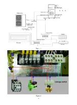
1) System installation diagram to see Figure 10.
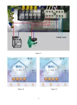
2) Electrical wiring diagram to see Figure 11.
(
If do not need to install auxiliary heating, DO not
connect point 1,4 AC contactor
)
3) Controller panel setting to see Figure 12.and Figure 13. . The inlet water setting temp. of the
heating or cooling mode can be adjusted by Target temperature setting interface.
4) Terminal of 3-way valve is no need for wiring.
5) The head of circulation pump should be big enough. Its actual water flow cannot be less than
water flow on nameplate .
Figure 10
Содержание V1 Series
Страница 9: ...8 V1 18 V1 23 V1 28 V1 35...
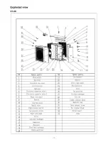
Страница 10: ...9 Exploded view V1 08...
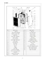
Страница 11: ...10 V1 13...
Страница 12: ...11 V1 18 23...
Страница 13: ...12 V1 28 35...
Страница 16: ...15 Figure 2 Figure 3...
Страница 18: ...17 Figure 7 Figure 8...
Страница 20: ...19 Figure 11 Figure 12 Figure 13...
Страница 23: ...22 Electrical Wiring Diagram 1 Single phase system V1 08...
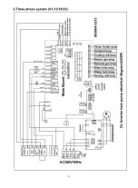
Страница 24: ...23 2 Three phase system V1 13 18 23...
Страница 25: ...24 3 Three phase system V1 28 35...

