background image

- 42 -

Common Faults and Debugging

The user must hire the professional maintenance staff to fix if the unit has any problems

during working. The maintenance staff might refer to the chart to debug.

Error Status

Possible reason

Solution

Heat pump not

running

Power fault

Wiring loose

Fuse blow fused

Thermal Overloaded protector off

Low pressure too low

Put off the power switch, check the

power supply

find out the causes and repair

Replace the fuse blow

test the voltage and current

Water pump is

working but without

water cycle or

water pump high

noise

Lack of water in the system

with air in the water system

the valves are not all open

filter is dirty and blocked

Check the system replenishment

device and replenish the system

discharge the air in the water system

Open the water system valve

Clean the water filter

Low heating

capacity

Lack of refrigerant

Bad heat preservation of water

system;

Dry filter blocked

Bad heat dissipation of air heat

exchanger

Not enough water flow

Leakage detecting and supply

refrigerant

Reinforce the heat preservation of

water system

Change the dry filter

Clean the air heat exchanger

Clean the water filter

Compressor not

working

Power failure;

Contactor of compressor damage;

wiring loose

Compressor

overheat protection

outlet water temp. Too high;

Not enough water flow

Compressor overload protector

tripped

Find out the causes and solve the

power failure

Change the contactor of compressor

Find out the loose point and repair

Check the unit pressure and Exhaust

gas temp.

Reset the outlet water temp

Clean the water filter and discharge

the air in the system

Check the running current and whether

overload protector damage

compressor

running noise too

high

Liquid refrigerant enter the

compressor

The inner parts of compressor

damage

Too Low voltage

Check the expansion valve whether

out of effect

Replace the compressor

Check Power Voltage

Fan not working

The fastening screw of the fan

loose

Fan motor damage

Contactor damage

Reinforce the screw

Replace the fan motor

Replace the contactor

Compressor

running but heat

pump not heating

Refrigerant is all leaking out

Compressor fault

Compressor reversal

Check leakage and charging the

refrigerant

Replace the compressor

Exchange the phase order of

compressor

Low water flow

protection

Not enough water flow in the

system

Water switch fault

Clean the water filter and discharge

the air in the system

Check the water switch and replace it

Содержание V1 Series

Страница 1: ...VI DC Inverter Heat Pump with WIFI APP OPERATING INSTRUCTION MANUAL Valdemar Energy Denmark www valdemarenergy com IMPORTANT SAFETY INSTRUCTIONS READ AND FOLLOW ALL INSTRUCTIONS SAVE THESE INSTRUCTION...

Страница 2: ...unding and Over Current Protection 21 Electrical Wiring Diagram 22 Section 3 Operating Heat Pump 25 Controller Panel 25 1 Display Icon 25 2 Definition of Buttons 26 3 Wire Controller Operation 27 Gene...

Страница 3: ...s take precedence over national codes In the absence of local codes refer to the latest edition of the National Electric Code NEC in the local government Electric Code CEC for installation DANGER Risk...

Страница 4: ...taller or service agent and must conform to all national state and local codes and or safety regulations 2 This EVI DC Inverter Air Source Heat Pump is specifically designed for domestic hot water hou...

Страница 5: ...Inverter air source heat pump Note Before installing this product read and follow all warning notices and instructions Only a qualified service person should install the heat pump Materials Needed fo...

Страница 6: ...t R32 1 3kg R32 1 6kg Compressor Brand Panasonic IP Grade Level of Protection IPX4 IPX4 Anti electric Shock Rate I I Noise dB A 53 55 Water Pressure Drop kPa 31 25 Water Circulation m H 1 4 2 2 Diamet...

Страница 7: ...onic IP Grade Level of Protection IPX4 IPX4 IPX4 IPX4 Anti electric Shock Rate I I I I Noise dB A 57 58 62 66 Water Pressure Drop kPa 35 45 40 45 Water Circulation m H 3 1 4 0 4 8 6 0 Diameter of Pipe...

Страница 8: ...ical connections 2 Field assembly if required 3 Appropriate site location and clearances 4 Proper electrical wiring 5 Adequate water flow This manual provides the information needed to meet these requ...

Страница 9: ...8 V1 18 V1 23 V1 28 V1 35...

Страница 10: ...9 Exploded view V1 08...

Страница 11: ...10 V1 13...

Страница 12: ...11 V1 18 23...

Страница 13: ...12 V1 28 35...

Страница 14: ...ccess areas The heat pump must be placed to provide clearances on all sides for maintenance and inspection 1 The heat pump installation area must have good ventilation and the air inlet outlet must no...

Страница 15: ...uggested Installation Methods 1 For heating hot water installation 1 System installation diagram to see Figure 2 2 Electrical wiring diagram to see Figure 3 If do not need to install auxiliary heating...

Страница 16: ...15 Figure 2 Figure 3...

Страница 17: ...wiring diagram to see Figure 8 If do not need to install auxiliary heating DO not connect point 1 4 AC contactor 3 Controller panel setting to see Figure 9 4 Terminal of 3 way valve is no need for wi...

Страница 18: ...17 Figure 7 Figure 8...

Страница 19: ...DO not connect point 1 4 AC contactor 3 Controller panel setting to see Figure 12 and Figure 13 The inlet water setting temp of the heating or cooling mode can be adjusted by Target temperature settin...

Страница 20: ...19 Figure 11 Figure 12 Figure 13...

Страница 21: ...age and pressure test 4 All the pipelines and pipe fittings must be insulated to prevent heat loss 5 Install a drain valve at the lowest point of the system to enable the system to be drained during f...

Страница 22: ...to select the cables circuit breakers and isolator breakers Grounding and Over Current Protection In order to prevent electrical shock in case of leakage from unit install the heat pump according to l...

Страница 23: ...22 Electrical Wiring Diagram 1 Single phase system V1 08...

Страница 24: ...23 2 Three phase system V1 13 18 23...

Страница 25: ...24 3 Three phase system V1 28 35...

Страница 26: ...tons in orange 1 Display Icon Mode Meaning Heating mode Hot water mode Cooling mode Heating and Hot water Mode Hot water function as priority Cooling and Hot water Mode Hot water function as priority...

Страница 27: ...ture of heating cooling at heating hot water mode cooling hot water mode Temp display real time water tank temperature at only hot water mode or real time return water temperature of heating cooling a...

Страница 28: ...n interface press MODE button for around 1 seconds to switch the running modes 5 modes optional heating only cooling only DHW only heating hot water cooling hot water Under heating hot water mode or c...

Страница 29: ...rmal mode Heat pump has Smart Powerful Silent Operating states to choose Vacation mode description When this mode is enabled The heat pump runs in heating mode only with a Target temperature of vacati...

Страница 30: ...d exit or press Esc to exit without saving CLOCK SETTING In the main interface press to enter clock setting interface as below Press the date Year Month Day column or hour Hour Minute column the keybo...

Страница 31: ...perform on that day When the weekday button turns gray the timer will not perform on that day In the TIMER column users can set 4 pairs of timer at maximum The timer is invalid when the turn on time e...

Страница 32: ...pening of assistant expansion valve 13 Compressor current 14 Heat sink temp 15 DC bus voltage value 16 Compress actual frequency 17 Low pressure gauge pressure value R410 Real time data Bar 18 High pr...

Страница 33: ...temp 15 50 35 P06 Setting temp of exhaust gas too high protection TP4 50 125 120 P07 Setting temp of exhaust gas too high recover tp0 50 125 95 P08 Water temp compensation 5 15 inlet outlet water wate...

Страница 34: ...ressor s Frequency operation mode after constant Temperature 0 Decrease Frequency after constant Temp 1 Non Decrease Frequency after constant Temp 0 P26 Pipeline E Heater Enable Ambient Temp 20 20 0 P...

Страница 35: ...temperature Antisepsis program will be forced to exit Target Temperature Auto Adjustment Logic Under Heating Mode The target temperature under heating mode can be automatically adjusted according to t...

Страница 36: ...05 Restart difference P01 4 Water pump during Working States When the above conditions are met The Electric Heater will turn on Shut down condition 1 Under Cooling or Hot Water Mode 2 Without Heating...

Страница 37: ...on t adjust by yourself 2 2 Unit have enough refrigerant and lubricating oil don t fill or replace them if need fill owing to leak please refer to the quantity on nameplate if refill refrigerant need...

Страница 38: ...record in FAULTY column inside the SETTING interface The following Common Error Codes will be displayed on the controller panel Error Code Definition of Error or Protection Er 03 Water flow failure E...

Страница 39: ...o high pressure protection When there s Er 20 error in the system it will display below detailed error code from 1 to 348 Among them 1 128 are in the first class when will be displayed as priority 257...

Страница 40: ...igh voltage Input voltage too high PFC Module failure Replace inverter module 64 Radiator over temperature Main unit fan motor failure air duct blockage Inspect fan motor air duct 128 Radiator tempera...

Страница 41: ...se turn off the heat pump and disconnect it from the mains power supply when not in use for a prolonged period of time Troubleshooting Use the following troubleshooting information to resolve issues p...

Страница 42: ...m is normal or not Check the pipe splice and the air injection valve whether have greasy dirt Make sure not any refrigerant leakage in the cooling system 7 Don t stack any sundries around the unit in...

Страница 43: ...changer Clean the water filter Compressor not working Power failure Contactor of compressor damage wiring loose Compressor overheat protection outlet water temp Too high Not enough water flow Compress...

Страница 44: ...n be connected within 10s after the first power on and it needs to be connected by pressing buttons after 10 seconds 10s is the delay for wifi to enter low power consumption Manually enter the smart d...

Страница 45: ...s bluetooth Turn on the WIFI function of the mobile phone and connect to the WIFI hotspot The WIFI hotspot must be able to connect to the Internet normally as shown in the figure Connect the WIFI hots...

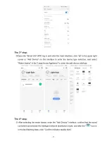
Страница 46: ...Input Confirm the Correct Wifi Password Click Next to Start Matching Wifi The 5th step When the connection is successful and the system prompts Added successfully then the network configuration is suc...

Страница 47: ...RESET to enter the smart distribution mode the icon on the main interface flashes and the mobile phone can start to configure the network Exit the network configuration status after 3 minutes the icon...

Страница 48: ...ce type selection and select Water Heater in the Large Home Appliance to enter the add device interface The 4th step After selecting the water heater enter the Add Device interface confirm that the wi...

Страница 49: ...ile phone and click Next to directly enter the device connection state Remarks When the wired controller s WIFI module is connected to the WIFI hotspot the icon flashes fast The 5th step When the Scan...

Страница 50: ...ion network mode The 1st step Select AP MODE on the WIFI interface of the wired controller click WIFI RESET to enter the AP network configuration mode the icon on the main interface flashes and the mo...

Страница 51: ...d enter the main interface click in the upper right corner or Add Device on the interface to enter the device type selection and select Water Heater in the Large Home Appliance to enter the add device...

Страница 52: ...bile phone click Next and the Connect your mobile phone to the device s hotspot pops up follow the prompts and click Go to Connect Enter the mobile phone s WIFI connection interface find the connectio...

Страница 53: ...nection is successful and the system prompts Added successfully then the network configuration is successful In this interface you can change the device name at select the device installation location...

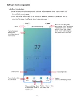
Страница 54: ...e Heat Pump device s operation page Fault information display fault information when a fault occurs return More You can change the device name select the device installation location check the network...

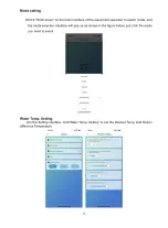
Страница 55: ...ent operation to switch mode and the mode selection interface will pop up as shown in the figure below just click the mode you need to select Water Temp Setting In the Setting interface click Water Te...

Страница 56: ...if the water tank temperature 55 both the compressor and electric heater will start When the water tank temperature 70 and the protection temperature lasts for 30minutes 65 exit the high temperature...

Страница 57: ...y Electric Heater for Water Tank Start conditions all below conditions must be met at the same time 1 In hot water mode 2 The compressor runs for start time for electric heating of water tank 30 minut...

Страница 58: ...nlet Water Temp Heating Set Temp P05 Restart difference P01 8 Water pump during Working States When the above conditions are met The Electric Heater will turn on Shut down condition 7 Under Cooling or...

Страница 59: ...ates in the following sequence After successful sharing the list will be increased and show the shared person To delete the shared person long press the selected user the delete interface will pop up...

Страница 60: ...operate and control the device Device removal APP removal Click in the upper right corner of device operation main interface to enter device details interface and click Remove Device interface to ente...

Отзывы: