E
N
G
L
IS
H
47
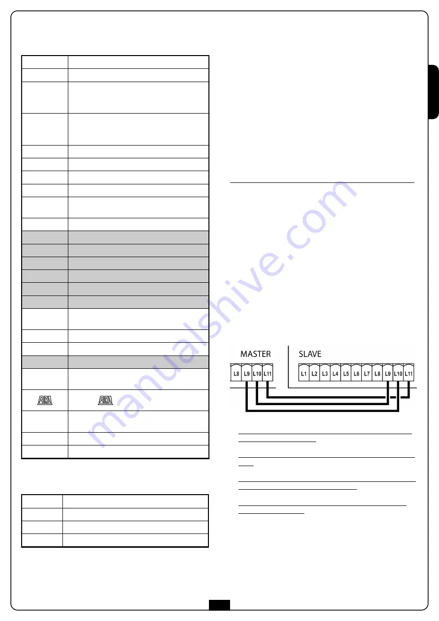
L1
Antenna
L2
Antenna shield
L3
START1 – Activation input 1 for connection of
traditional devices with N.O. (normally open)
contact.
L4
START2 - Activation input 2 for connection of
traditional devices with N.O. (normally open)
contact.
L5
STOP Command. N.C. (normally closed) Contact
L6
Common (-)
L7
Photocell. N.C. (normally closed) contact
L8
Safety ribbon. Contact N.C or resistive
L9 (SL-IN)
L10 (SL-OUT)
Connection terminals for two synchronized
control units.
L11
Common (-)
H1
Lock-Out N.C. (normally closed) Contact
H2
Common (-)
H3 - H4
Encoder
H5
Encoder power supply (+5V)
H6
Common (-)
H7 - H8
Motor output
G1 - G2
Power output 24VDC for photocells and other
accessories
G2 - G3
Power feed TX photocell by functional Test
G4 - G5
Electromagnetic vacuum gripper power output
G6 - G7
Blinking 24V
B1 - B2
Contact N.A. (max. 230V/120V-5A) for
additional courtesy light or blinking led
Interface
OVERLOAD
It signals an overload on the accessories power
supply
BAT+
Pole + optional battery package (code 161212)
BAT-
Pole - optional battery package (code 161212)
L
Power supply feeding phase 230VAC / 120VAC
N
Neutral feed 230VAC / 120VAC
MAINS
It signals that the control unit is being powered
F1
Protection fuse 2.5 A
TABLE OF ELECTRICAL
CONNECTIONS
NOTE: the evidenced connections are already wired at the
factory
m
ATTENTION: Tighten a tie-wrap next to the terminal
strip around the two feeder cables that arrive on terminals
L and N to reduce the possibility of accidental detachment.
CONNECTING THE ECO-LOGIC
SYSTEM
If the automation device is powered by means of the ECO-LOGIC
system, proceed as follows:
1.
disconnect the faston connector from the POW+ and POW-
terminals
2.
connect POW+ to terminal 3 of the black connector on the
accumulator unit
3.
connect POW- to the ground terminal of the black connector
on the accumulator unit
NOTE: it is recommended the batteries be pre-charged prior
to installation
PLEASE NOTE: activate the Energy Saving function
Read the instruction manual included with the device thoroughly
SYNCHRONIZED OPERATION OF
TWO BARRIERS
In order to control two barriers in synchronized way proceed as
follows:
1.
Mark one of the two control units as MASTER, the other one
as SLAVE
2.
Connect terminal
L9 (SL-IN)
of the MASTER control panel with
terminal L10
(SL-OUT)
of the SLAVE control panel
3.
Connect terminal
L10 (SL-OUT)
of the MASTER control panel
with terminal
L9 (SL-IN)
of the SLAVE control panel,
4.
Connect the common
L11
of the MASTER control panel with
the common
L11
of the SLAVE control panel
5.
Connect all the activation, arrest, and photocells devices only
to the MASTER control unit
6.
Insert the interlocking receiver to MRx on the MASTER control
panel
7.
Connect eventual emergency obstacle sensors separately, each
one to its own corresponding control unit
8.
Set in action the auto learning of end-stop feature on both
command control units
9.
In the programming menu of the control unit SLAVE set up
the following functions:
- set up the operation of input START (
Strt
menu) as
SLA
- disable the photocell input (disabled by default)
- disable the STOP input (disabled by default)
Содержание 36A004
Страница 2: ......
Страница 9: ...ITALIANO 7 Fig 3...
Страница 11: ...ITALIANO 9...
Страница 16: ...ITALIANO 14...
Страница 34: ...ITALIANO 32 INSTALLAZIONE DELL ACCESSORIO 163604...
Страница 41: ...ENGLISH 39 Fig 3...
Страница 43: ...ENGLISH 41...
Страница 48: ...ENGLISH 46...
Страница 66: ...ENGLISH 64 INSTALLATION OF THE ACCESSORY 163604...
Страница 73: ...FRAN AIS 71 Fig 3...
Страница 75: ...FRAN AIS 73...
Страница 80: ...FRAN AIS 78...
Страница 98: ...FRAN AIS 96 INSTALLATION DE L ACCESSOIRE 163604...
Страница 105: ...ESPA OL 103 Fig 3...
Страница 107: ...ESPA OL 105...
Страница 112: ...ESPA OL 110...
Страница 130: ...ESPA OL 128 INSTALACI N DEL ACCESORIO 163604...
Страница 131: ......
Страница 132: ......


