


A-2
Appendix A: Sensors
Keyence FS-V21/FS-V22 Sensor Amplifiers
61004015.fm
Keyence FS-V21/FS-V22 Sensor Amplifiers
The Keyence FS-V21 and FS-V22 sensor amplifiers (shown in Figure A.1) are used on the TM-50 for both the low
cover tape sensor and the empty pocket detector. The V21 is the low cover tape amplifier unit and V22 is the EPD
amplifier unit. The FS-V22 is designed to be attached electrically to the FS-V21 and share VDC and GRND sources,
so that the FS-V22 unit draws ground and power through the FS-V21. Otherwise, the two units function independent
of one another.
Selecting the Output Mode
The FS-V21/FS-V22 sensor-amplifiers can be set to two Output Modes: light-ON or dark-ON. This determines under
what conditions the sensor is triggered and the Operation Indicator is lit. In light-ON mode, the sensor will be triggered
when the current value (CV) of detected light from the emitter is higher than the preset value (PV). In dark-ON mode,
the sensor is triggered when the CV of detected light is lower than the PV. Essentially, in light-ON Output Mode the
sensor detects when an obstruction occurs (causing reflected light to increase) and in dark-ON Output Mode the sen-
sor detects when an obstruction is removed (causing reflected light to decrease).
1. Press the Output Selector button. The CV indicator will display the current mode.
2. Press the Manual button within 5 seconds of having pressed the Output Selector button. The Output Mode will be
toggled.
3. The CV indicator will return to its normal display after 5 seconds have elapsed.
Locking the Keys
It is sometimes desirable to lock the keys of the sensor amplifiers so that the currents settings are not inadvertently
changed.
1. Hold down the Manual button and the Mode button simultaneously for at least three seconds.
2. The CV indicator will display “Loc” to indicate that the lock is in place.
3. Repeat the same procedure to unlock the keys. The display will flash the message “unL”.
Two-point Calibration
1. With an obstructing object between the sensors (ideally, a full reel of cover tape), press and release the SET but-
ton. The PV indicator will be lit.
2. Remove the obstruction between the sensors and press SET again. The amplifier will return to its normal operat-
ing mode. The number shown on the PV indicator should change.
3. The sensor’s operation indicator should be lit while there is no obstruction between the sensors.
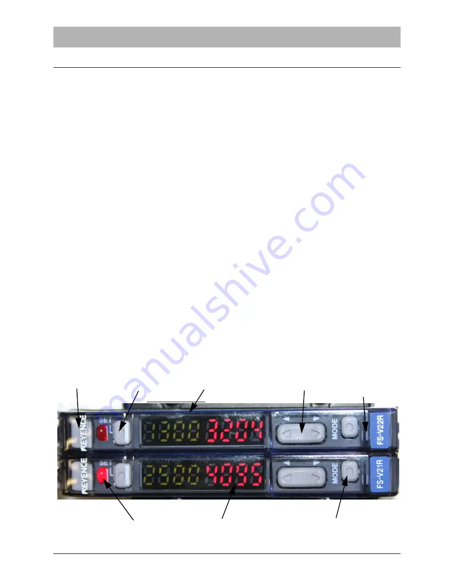
Figure A.1
Fiber Lock Lever
Set Button
Preset Value (PV) Green Indicator
Manual Button
Output Selector
Operation Indicator
Current Value (CV) Red indicator
Mode Button
Button
Содержание OEM TM-50 SMD
Страница 2: ......
Страница 4: ......
Страница 10: ...Safety Warning Labels 61685113 fm vi ...
Страница 28: ...16 OEM TM 50 User s Guide Machine Overview 61685225 fm ...
Страница 29: ...Chapter 2 Controller Contents The OEM TM 50 Controller 16 Extended Software Option 22 Using the Vision Port 25 ...
Страница 43: ...6174007 fm Using the Vision Port Chapter 2 Controller 29 Vision Hookup Example Figure 2 33 ...
Страница 74: ...60 OEM TM 50 User s Guide Electrical Connections 6174322 fm Figure 4 6 ...
Страница 95: ...61004015 fm Appendix A Sensors A 1 Appendix A Sensors ...
Страница 102: ...Service and Parts Contacts 61053915 fm Page 2 ...
Страница 104: ......
Страница 106: ...TM 50 OEM Sensors Spare Parts List D219368 2 fm Page 1 of 1 ...
Страница 108: ......
Страница 110: ......
Страница 111: ......
Страница 112: ...751 Summit Avenue Mankato MN 56001 507 387 2039 FAX 507 387 2257 www vtekusa com Email info vtekusa com ...


