Page 37
7.5
Channel Crossover and Equalization Procedure
Audio channel equalization consists of two steps:
1.
Crossover adjustment (if crossovers used).
2.
Channel Equalization.
7.5.1
Crossover Adjustment
A suggested crossover adjustment procedure is listed below. It should be skipped if the JSD-100 internal crossovers
are not being used. If an external pink noise generator is to be used with the internal RTA, enable the internal pink
noise generator, then disable it. Enabling the internal pink noise generator configures the internal RTA for proper
operation.
1.
Ensure that the proper speaker configuration (biamp or triamp) is selected by the Channel Config button.
2.
Position the RTA microphone in the auditorium as specified by SMPTE ST 202:2010 (about 2/3 of the way back
from the screen and 2/3 of the way from a side wall of the auditorium). The microphone is normally 1.0 to 1.2
meters (3.3 to 4.0 feet) from the floor, or “ear level” for a typical audience member.
3.
Plug the microphone in to the PA or CAL microphone input of the JSD-100. Set the RTA input to the
appropriate microphone input.
4.
On the Stage Output tab, slide all the level controls to minimum level.
5.
Turn the power amplifier gains all the way down.
6.
Set the JSD-100 fader to 7.0.
7.
Under the XO, Etc. Tab, press the Speaker button and select the desired speaker from the speaker library.
8.
Under the Stage Outputs tab, select pink noise and press the Gen button for the left channel.
9.
Turn up the amplifier gains as far as possible without exceeding 85dB SPL in the auditorium.
10.
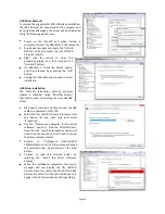
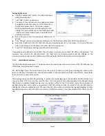
On the X-Overs tab, press the View button to make the RTA display visible.
11.
Adjust the RTA Gain (control becomes visible when cursor over graph area) until the RTA results become
visible on the RTA display.
12.
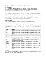
Adjust the band gains as necessary for the flattest RTA response possible. For optimum noise performance,
JSD-100 systems with analog output boards use a single electronic potentiometer for both the channel output
trim and the crossover band gain. If, for example, the channel output trim is set to -6dB, and the crossover
band gain setting is set to -10dB, the potentiometer is set to -16dB. The potentiometer is limited to a -22dB to
+8dB range. Ensure the algebraic sum of these two settings does not go outside this -22dB to +8dB range.
13.
If there appears to be a notch in the response at the crossover frequencies, try pressing an Invert button to
switch the phase on that band.
14.
Press Copy and copy the crossover settings to each of the other screen channels.
15.
Go back to the Stage Output tab, turn off the generator on the left channel and turn it on for the next channel.
Repeat the above process for each channel.
16.
If the output board is a 16 channel analog board and internal crossovers are being used, apply an external pink
noise source to left, center, or right channels of a JSD-100 input. This may be an AES generator such as the USL
DAT-100, an analog pink noise generator, or test content that has pink noise.
17.
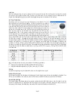
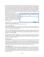
Set the rear panel DIP switches according to the following table:
18.
On the XO, Etc. Tab, press the Bypass button to put the JSD-100 in bypass.
Speaker Configuration
SW1 SW2 SW3 SW4
Biamp 330Hz crossover ON
ON
OFF
OFF
Biamp 1kHz Crossover
OFF
OFF
ON
ON
Triamp
ON
OFF
OFF
OFF
Full Range
OFF
OFF
OFF
OFF


