Page 17
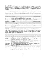
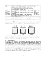
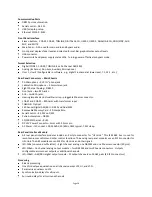
Internal crossovers on systems with 16 or more outputs. Crossovers support biamp and triamp of up to five
screen channels plus individual parametric equalization on one to three LFE outputs. Crossover includes a
speaker library and allows for user defined speaker systems.
Sleep Mode
With an Ethernet command or preset timeout, the unit can go into a sleep mode. Another Ethernet command,
“button press,” or automation pulse will wake up the unit.
Bypass Mode
In an emergency situation, the JSD-100 can be switched off, automatically enabling the bypass circuitry. Front
panel buttons, LEDs and fader will still function, allowing the operation of the unit in various analog and digital
formats. Final output is a monophonic signal feed to the left and right channels. The AES output module provides
a single balanced analog audio output for bypass. Note: The 12 VDC bypass power supply must be connected for
this functionality.
Graphical User Interface
The JSD-100 Graphical User Interface (GUI) operates under Windows XP, Windows 7, and Windows 8. It
communicates with one or more JSD-100 systems simultaneously over USB, Ethernet, or RS232. The GUI is used for
system configuration including auditorium equalization (both manual and automatic equalization).
Dynamic Range:
Typically 105dB.
Power Requirements:
100-240VAC, 50/60Hz, 30 watts maximum (18 watts typical, 7.5 watts sleep).
Dimensions:
Standard 2U rack-mount chassis.
Agency Approvals:
UL, cUL, CE and FCC.
6.
Installation
6.1
Initial Power Up
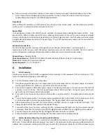
A quick power-up test of the JSD-100 is suggested before mounting it in the equipment rack and wiring it up. This
test can quickly detect shipping or other damage.
Turn the AC power switch to the off position.
Using the supplied AC line cord or one appropriate for the installation location (the power supply is a universal
input supply 100-240 VAC, 50/60 Hz), connect the JSD-100 to the AC line.
Connect the supplied 12 VDC bypass power supply to the bypass power input on the rear panel of the JSD-100
and plug it in to the AC line. The front panel “Bypass Mode” LED should flash, the bypass power LED should
light, and one of the format buttons should light.
Press each of the format buttons and the mute button, one after another. The appropriate button should
light.
Turn on the AC power switch. The display should immediately light, but be blank. All the green power LEDs
on the bottom right of the front panel should light. The “Bypass Mode” LED should stop flashing.
After approximately 25 seconds, the format buttons will flash and then a single format LED will light. The
display should show the fader level and the selected format.
Press each of the format buttons, verifying that the corresponding LED lights and that the display changes
accordingly. Note that the format button LEDs for digital formats will flash when no digital input is provided.
Press the mute button verifying that its LED toggles each time the button is pressed.
Rotate the fader in each direction verifying that the fader numbers on the display change.
6.2
System Hardware Mounting, Grounding and Ventilation
The JSD-100 is designed to mount in a standard 19 inch (482.6mm) rack and is two rack units high (3.5 inches,
137.8mm). The JSD-100 should be mounted at “eye level” in the equipment rack for optimum display contrast and
visibility. We recommend vented panels (USL part number VP-1) above and below the JSD-100 whenever space


