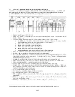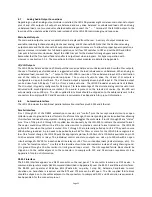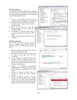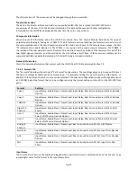
Page 27
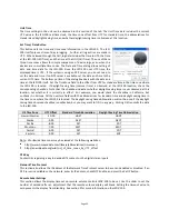
auditorium. Note that crossovers and 13.1 will not be available on systems with the 8 channel output card. On
these 8 channel output systems, the last pair of channels can be configured for a 7.1SDDS installation, which has Lc
and Rc speakers. These last two channels could alternatively drive rear surround speakers (Lrs and Rrs) by choosing
7.1DS. With the 16 channel analog or 32 channel AES output boards, biamp, triamp, and 13.1 speaker
configurations are available. See section 4.3 for a speaker location chart for various “soundfield configurations”.
Headroom
The headroom setting adjusts the system gain so the nominal level is a specified number of dB below the digital
clipping level (0 dBFS). Generally, headroom is set at 26dB. If several bands of equalization are set to high levels of
boost, you may wish to increase the headroom to avoid clipping.
FLASH Save Settings
Pressing this button saves the current configuration to flash memory inside the JSD-100. The JSD-100 will load this
configuration the next time it is powered up. Because of the importance of saving the configuration, you are also
given another opportunity to save the settings when disconnecting from the JSD-100.
SD Card Backup
Pressing this button writes the current configuration to the SD or MMC card plugged in behind the removable
panel on the rear of the JSD-100. If the cover is removed, you will see a red LED to the left of the card light as the
card is written. A backup to the SD card can fail if no card is present, if the card is write protected, or if the card is
not formatted correctly (FAT16 or FAT32). The data written on the card is a series of commands in a text file
(JSD100.CFG). If a JSD-100 needs to be swapped out, the SD/MMC card can be moved from the old unit to the new
unit to copy all the old settings to the new unit. To load data from the SD/MMC card, hold down buttons 9 and 10
(AUX and MIC) when turning the JSD-100 main power switch on. Continue to hold the buttons down until the
display says “Loading From SD Card”. The display will show the progress of the load and then return to the normal
display.
7.4.4
Main Fader
The current main fader level can be viewed and changed using the slider. These are equivalent to the front panel
main fader knob and display. The fader level display also shows a small bar graph that displays the measured
output level on each channel.
7.4.5
Front Panel View
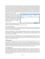
Below the above-described buttons is a view of the JSD-100 front panel. When connected to the JSD-100, this
view duplicates the look of the front panel. In addition, the buttons can be pressed to change format or mute the
system, just as on the front panel. The LED above the format button lights when that format is selected. It flashes
if the format is a digital format and no digital signal is present on the selected input.
7.4.6
Tabs
The remainder of the GUI
window contains tabs that
divide
the
remaining
configuration data into logical
groups. Each tab will be
discussed in sequence.
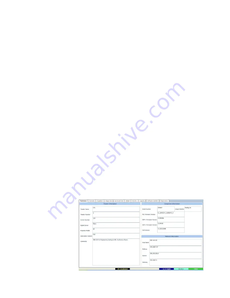
7.4.6.1 Summary Tab
The “Summary” tab (shown
below) gives a broad view of
the JSD-100 and its installation.
The Theater Information fields
may be changed as needed.

