background image

26

Install Smart Charger / Charge Controller  

Power Source (AC or Solar)

The Ranger gate operator’s battery is charged by the USAutomatic smart charger / charge controller. 

The USAutomatic smart charger / charge controller can be powered by an AC transformer supplied 

with Ranger AC Models 

OR

 a solar panel supplied with Ranger Solar models. The AC Transformer 

and the Solar Panel are equipped with a DC plug for easy connection to the smart charger / charge 

controller.

Ranger AC Charged System

The AC model Ranger gate operator comes with a low voltage transformer 

which plugs into the charge controller and can easily provide 575 cycles of 

operation a day without decreasing the battery charge. In the event AC power 

goes out the operator will operate for weeks on the battery (if cycles per day are 

below 20) before needing service. Again, accessories connected to the operator 

are critical. Always use Solar Friendly accessories to help avoid premature 

battery failure in cases of power outages.

The unique design of the charging system allows the transformer to be installed away from the gate 

area if needed. This means that on AC charged systems, the transformer’s low voltage wire can be 

extended avoiding the expense of having an electrician install 120 VAC at the gate area.
Refer to the AC power source cable extension chart below for the exact wire size to be used. 
NOTE: AC Transformers are not designed to get wet. Likewise, all splices should be made in a dry 

enclosure or outdoor box. For convenience use the USAutomatic Charge Cable Extension Pigtails  

PN #630038.

Transformer Extension Wire Size

0 to 100 feet

101 to 250 feet

251 to 500 feet

501 to 750 feet

750 to 1000 feet

18 gauge wire

16 gauge wire

14 gauge wire

12 gauge wire

10 gauge wire

NOTE:

  USAUTOMATIC RECOMMENDS A SURGE PROTECTOR ON ALL AC  

CHARGED INSTALLATIONS.

Ranger Solar Charged System

Utilizing the USAutomatic Solar Panel kit, you may use a solar panel 

to charge the battery. Typically only one panel will be required. The 

Ranger gate operator is capable of a high number of cycles per day. 

For information on what you can expect from a solar charged system 

see Appendix. Accessories that are added to your gate operator must 

be solar friendly accessories and they will be identified as such. For a 

complete list of accessories, please visit www.usautomatic.com

14

14

a

14

b

Содержание Ranger I

Страница 1: ...Heavy Duty Battery Powered Solar or AC Charged Ranger I Single Swing Gate Operator Ranger II Dual Swing Gate Operator Installation Owners Manual ...

Страница 2: ...After all adjustments have been made to the sensitivity current sense circuit secondary entrapment devices and all other external devices installed the safety devices must be checked again Failure to adjust and retest the gate operator can increase the risk of injury or death 13 Verify that the emergency release manual release pin can be easily removed 14 KEEP GATES PROPERLY MAINTAINED Tighten all...

Страница 3: ...wer needed for the transformer BATTERY REQUIRED FOR OPERATION Battery not included Recommended battery type Battery 12 volt Group U 1 sealed maintenance free 30 amp hour minimum Using a smaller amp hour battery may cause damage to the charging system The wiring harness has two 1 4 ring terminals to connect to battery posts CAUTION Do not install wet cell battery into control box this type of batte...

Страница 4: ...ctured before Jan 12 2016 that is not being upgraded to meet the current UL325 standard the Pre 2016 jumper must be installed into J5 terminal block for proper operation USAutomatic recommends upgrading all systems to current UL325 standards UL325 identifies four different classes of gate operators These classes are RESIDENTIAL VEHICULAR GATE OPERATOR CLASS I A vehicular gate operator or system in...

Страница 5: ...valent Zone B Gate opens toward an immoveable object with less than 16 inches of clearance recommended monitored entrapment protection type B1 photo eye or equivalent If space is less than 16 entrapment protection in this area is required ASTM F2200 7 1 1 1 and 7 1 1 2 Zone C If distance from center of hinge rotation point to corner of column post or immovable object is greater than 4 inches recom...

Страница 6: ...tall Linear Actuator Cable 23 Splicing Linear Actuator Cable Cable and Dual Gate Cable 23 12 Installing Monitored Entrapment Protection Devices 24 Monitored Photo Eye Installation 24 Monitored Contact Edge Installation 25 13 Install Battery 25 14 Install Smart Charger Charge Controller Power Source AC or Solar 26 15 Connect Power Source to Smart Charger Charge Controller 27 16 Charge Controller Op...

Страница 7: ... to eliminate the chance of the person operating the gate from coming in contact with the moving gate Do not install external buttons which can be used to operate the gate within the reach of children Safety Signs are installed one on each side of the gate and visible in the gate area All hard wired sensors used for monitored entrapment protection devices and their wiring are installed in a manner...

Страница 8: ...Part 030210 2 per AC Charging Transformer Part 520004 with Ranger AC Models Solar Charging Kit Part 520025 with Ranger Solar Models External Reset Button Part 630060 1 per Safety Signs Part 601020 2 per Optional Accessories LCR Items See accessories section for complete list and descriptions 4 Button Transmitter Part 030212 Push to Operate Button Part 030215 Wireless Keypad Plastic Part 050500 Wir...

Страница 9: ...l Release Pin Clip Part 610535 Ranger I 1 per Ranger II 2 per Nylon Washers Part 610528 Ranger I 2 per Ranger II 4 per Bronze Bushing Part 610530 Ranger I 2 per Ranger II 4 per Bolt Part 610512 Ranger I 1 per Ranger II 2 per SAE Flat Washers Part 610516 Ranger I 2 per Ranger II 4 per Lock Nuts Part 610518 Ranger I 1 per Ranger II 2 per Threaded Cable Strain Relief Conn Part 630022 1 per 12 Self Ta...

Страница 10: ... Lag type bolts are not recommended Loose or unstable linear actuator mounts will result in improper operation IMPORTANT CAUTIONS A Do not perform any welding with the actuator cable plugged into the control board or the battery connected Serious damage to the control board and or battery may occur if attempted B Do not attempt to hold control box and drill mounting holes with components installed...

Страница 11: ...ry for application questions and advice Example Convert one 20 gate into two 10 gates and use a dual gate operator Note The total gate opening cannot exceed 110 degrees The Ranger Gate Operator is recommended for Gates that meet the following descriptions Ornamental Iron 13 feet max length Max weight 400 lbs Ranch Gate 16 feet max length Max weight 300 lbs Farm Gate 20 feet max length Max weight 2...

Страница 12: ...roblems A wheel is generally a sign of a weak hinge system or a weak gate frame Is the gate frame of substantial strength without excessive weight Will the frame withstand normal wind load conditions without sway or vibration Will the gate close correctly without being hand guided or lifted to close Are the hinges suited for an automatic gate operator We recommend bearing type hinges to reduce fri...

Страница 13: ...30038 See Power Source Cable Extension chart for identifying the wire size needed for the distance required Transformer must be installed indoors or in a raintight enclosure Transformer should not be exposed to moisture 7 For Solar Charged System Where will the solar panel mount so that optimum sunlight is received Solar panel is provided with 15 feet of cable If extension is needed use power sour...

Страница 14: ...wings into the property and the operator pulls the gate open Push to Open Installation This installation method is commonly used where the drive slopes upward into the property and the operator pushes the gate open The gate swings outward away from the property 2 RETRACTED Gate Open RETRACTED Gate Closed EXTENDED Gate Closed EXTENDED Gate Open ...

Страница 15: ...rmine the location of the actuator mounting tube The actuator delivers force on the gate when operating Aligning the actuator mounts with a horizontal gate frame member is the best choice as shown here Installation of a horizontal brace may be necessary to prevent damage to vertical gate pickets Avoid mounting actuator on bottom rail of gate Unit will be more likely to be damaged by flooding and w...

Страница 16: ...st Wood or Aluminum Post Drill through mounted Drill through post and bracket Use carriage bolts with back plate not included 4a Actuator support bracket mounted horizontally on hinge post Actuator support bracket mounted vertically on hinge post Actuator support bracket mounted vertically on hinge post Actuator support bracket mounted vertically opposite hinge 3D Example On wood post Actuator sup...

Страница 17: ...below are for left hand installations Reverse for right hand installations Square Post Round Post Wood or Aluminum Post 4b Drill through mounted Drill through post and bracket Use carriage bolts with back plate not included Actuator support bracket mounted horizontally on hinge post Actuator support bracket mounted vertically on hinge post 3D Example ...

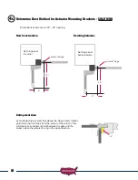
Страница 18: ...ment Area Avoid designing a system that places the hinge center rotation point more than 4 inches from the corner of the column This will create an entrapment point between the gate and the column when the gate is moving in the open direction Set hinge post in corner Set hinge post behind column center of hinge center of hinge 5 5 7 5 7 5 4c 4 ...

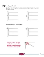
Страница 19: ...g location of the Actuator Support Bracket mount the support bracket in alignment with predetermined horizontal frame member as per the following examples Bracket must be level in all directions DO NOT mount support bracket in a manner that obstructs gate movement or creates a pinch point 5 ...

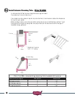
Страница 20: ...ull to open system Before welding in place ensure the actuator mounting tube is level in all directions and the pivot hole location on actuator mounting tube is at proper point per the dimension chart for the type of installation being performed PULL TO OPEN Actuator Hinge Mounting Tube Installation Dimensions Gate opening in degrees Dimension A Dimension B 90 degree opening 5 7 100 degree opening...

Страница 21: ...m Before welding in place ensure the actuator mounting tube is level in all directions and pivot hole location on actuator mounting tube is at proper point per the dimension chart for the type of installation being performed 7 Dim A 4 Dim B C u t L i n e PUSH TO OPEN Actuator Hinge Mounting Tube Installation Dimensions Gate opening in degrees Dimension A Dimension B 90 degree opening 7 4 100 degre...

Страница 22: ...g bracket using the provided hardware Assemble as shown below Tighten lock nut securely 7 Bronze Bushing Part 610530 Nylon Washer Part 610528 Nylon Washer Part 610528 Bronze Bushing Part 610530 Bolt Part 610512 SAE Flat Washer Part 610516 Mounting Tube Part 610420 SAE Flat Washer Part 610516 inch Lock Nut Part 610518 ...

Страница 23: ... in a level position to meet the fully open gate The contact point is where the gate bracket should be installed on the gate 3 Weld or bolt the gate bracket to the gate PUSH TO OPEN INSTALLATION ONLY The linear actuator was shipped from the factory set to the fully retracted position The steps below will determine where the gate bracket is to be installed on the gate 1 Swing gate to the fully clos...

Страница 24: ...prior to drilling When deciding where to mount the control box remember the actuator cable is 8 feet in length If possible mount the control box in a location that will allow the cable to be neatly routed If it must be longer than the 8 feet see Splicing Actuator Cable Step Also avoid choosing a mounting location that is near sprinklers We have provided knockouts for conduit fittings in the contro...

Страница 25: ... end and cut the black cable See Figure 2 Save this 8 pin connector and pigtail cable for step 8 3 Install a rain tight junction box on the Gate 2 hinge post below or near the actuator 4 Install the extension cable from the junction box at Gate 2 to the Ranger control box Route the cable through the bottom of the junction box and the Ranger control box Cut the cable longer than needed for future n...

Страница 26: ...stalling Monitored Entrapment Protection Devices Effective January 12 2016 A vehicular gate operator or vehicular barrier arm operator shall have provisions for or be supplied with at least two independent entrapment protection means as specified in current UL325 standard Table 31 1 At installation both entrapment protection devices must be installed and operational before gate operation is allowe...

Страница 27: ...d Contact Edge wiring for Entrapment Device Protection Contact Edge Connectons Ranger Control Board Connections N O connection J2 pin 6 Common J2 pin 2 or pin 7 Install Battery The recommended battery for all installations is a 12 volt Group U1 maintenance free battery 30 to 35 amp hours This type battery is commonly known as a lawn tractor or wheel chair battery The charge controller harness is s...

Страница 28: ... away from the gate area if needed This means that on AC charged systems the transformer s low voltage wire can be extended avoiding the expense of having an electrician install 120 VAC at the gate area Refer to the AC power source cable extension chart below for the exact wire size to be used NOTE AC Transformers are not designed to get wet Likewise all splices should be made in a dry enclosure o...

Страница 29: ...mount of shade or blockage will cause the Solar Panel to cease charging Something as tiny as a fingertip shadow will affect the Solar Panel The solar panel may be moved up to 500 feet from the control box to achieve adequate sunlight See power source cable extension chart below for proper wire size For convenience use the USAutomatic 75 Cable Kit Part 520016 or USAutomatic Charge Cable Extension P...

Страница 30: ...ight comes on NOTE Most batteries will not be completely charged when first connected and the charging light should come on when charge controller is first connected The fully charged light will come on once battery is fully charged When using a solar panel the charge controller is designed to only charge the battery when there is enough sun to do so If there is no sun then the lights on the charg...

Страница 31: ...Gate 2 connector Set control switch ON for the connector being used 17 Ranger Control Board External Reset Connector Sensitivity Adjustments DS1 Function Dip Switches Gate 1 Limit Adjustments Gate 2 Limit Adjustments Timer to Close Delay Adjustment LCR Receiver Connector System Reset Siren Connector Open Close Command J2 Terminal LED Indicator Button Gate 2 Plug Gate 1 Plug ...

Страница 32: ...Input is connected when in pre 2016 configuration 7 Common Ground 8 Photo Eye N C connection monitored entrapment DS1 switch 9 must be on when monitored eye is connected Not used in pre 2016 configuration 9 Free Exit Open Input normally open contacts Loop input or any hold open input such as a 7 day timer telephone access unit or maintain contact switch normally open contacts These devices open th...

Страница 33: ...alf second before gate begins to move and releases 3 seconds after the gate begins to move Gate Leaf Delay OFF No Function 6 Photo Eye Power Management Enable when ON 12 vdc will be present at J2 pin 12 whenever gate is in motion ON Provides 12vdc output for photo eye J2 Terminal 5 NOTE DO NOT connect photo eye directly to battery or premature failure will occur OFF No Function 7 Mag Lock Enable O...

Страница 34: ...4 should be in the ON position DS1 switch 6 and 9 ON DS1 switch 10 ON RANGER II PUSH TO OPEN Dipswitches 2 3 and 4 should be in the ON position DS1 switch 6 and 9 ON DS1 switch 10 ON NOTE PUSH TO OPEN INSTALLATIONS ONLY Push to Open installations do not require rewiring of the actuator harnesses The Ranger control board dipswitch 2 eliminates the need to do this Failure to turn dipswitch 2 ON will...

Страница 35: ...arthest gate s actuator cable and plug it into the Gate 2 actuator connector Ranger II Dual Gates with overlapping gates or electrical lock requiring gate delay See section 19 Operating Gate for the First time Before operating the gate for the first time please verify the following items 1 Linear actuator is in the retracted position If dual gate check both 2 Verify that DS1 switches on control bo...

Страница 36: ...nt dials located in the upper left corner of the control board These adjustments control the amount of current the control board will allow the motor to draw from the battery to operate your gate Minimum force is the least amount of current allowed This circuit is inactive for the first second of gate operation A typical adjustment setting is between 4 to 7 on the adjustment dial If a setting abov...

Страница 37: ... that the current sensitivity adjustment for the gate being tested be set at a setting no greater than 5 for this test Gate Opening Gate is stopped by an object after 1 second of operation Gate Closing Gate is stopped first time by an object after 1 second of operation Gate stops and reverses for 2 seconds Auto close if turned ON is disabled Requires a Push Button Close Open or Reset input before ...

Страница 38: ...it then Gate stops Gate stops Auto close if turned ON is still active Auto close if turned ON is still active Return to normal operation when the sensor is no longer actuated Return to normal operation when the sensor is no longer actuated Verifying Monitored Contact Edge Type B2 Entrapment device Operation Only Operate the gate and verify entrapment protection devices are working properly Use the...

Страница 39: ...e Transmitter right button can be programmed to hold gate open over riding the auto close feature if activated 2 Press and hold the right transmitter button down Red light on transmitter should be on 3 Press the P2 push button until the green LD light comes on 4 Release both buttons Transmitter right button to receiver programming is complete Receiver Programming Relay P2 programming from momentar...

Страница 40: ...smitters from Receiver Memory 1 Press the P2 button on the receiver until the green LD light comes on Then release P2 button 2 While LD light is on press the P1 and P2 buttons simultaneously and hold until the green LD light begins to blink slowly It should blink 4 times then all transmitter codes are erased Install Safety Signs Install the 2 warning placards in the gate area where they are visibl...

Страница 41: ... to be greased 3 Mounting bolts for correct tightness 4 Inspect weld points for cracks or other defects 5 Inspect wiring for cuts nicks or other defects 6 Inspect hinge post to ensure it is not moving or twisting 7 Verify proper operation of charging system refer to charge controller operation check 8 Verify monthly that the inside of the control cabinet remains clean and free of insects Do not sp...

Страница 42: ...k to negative post of the battery Connect the positive 12vdc wire from the magnetic gate lock to J2 Mag Lock terminal 6 NOTE On dual gates with a magnetic gate lock it is also necessary to turn DS1 switch 5 on to activate the Gate Delay Feature For Dual Gates see Gate Delay Feature Section Exit Sensor Solar friendly device Preferred Technologies CP 3 3W Part Number 070305 The driveway exit sensor ...

Страница 43: ...l to the receiver Valid access code was entered This is the Blue 5 key on the metal keypad NOTE Do not install keypad until Create Communication with Receiver P1 relay 1 has been completed Keypad Programming Create Access Code Code you use to operate the gate CAN NOT BE THE SAME AS THE MASTER PASSWORD 1 Enter the Master Password 11111 this is the factory default master password 2 Enter 9 If correc...

Страница 44: ...n 5 digits or B is required 4 Enter 8 5 Enter the Master Password again to verify 6 Press 8 If correct 2 short beeps New Master Password is set If 1 long beep is heard start over with step 1 Programming Master Password Back to Factory Default 11111 1 Enter 11111 2 Press 8 long beep 3 Enter PUK code PUK must be 5 digits 4 Press 8 5 Enter PUK code to confirm 6 Press 8 2 beeps Master password reset c...

Страница 45: ...ure Example of random positioning of the virtual dipswitches to create a Security Code is shown below To enter the Security Code enter the dipswitch number followed by the dipswitch position character The Security Code would be entered as 1 20 3 4 5 6 7 80 9 Dipswitch Position Switch 1 Switch 2 Switch 3 Switch 4 Switch 5 Switch 6 Switch 7 Switch 8 Switch 9 or B X X X 0 X X or A X X X X Use table b...

Страница 46: ...One set of photo eyes pointing across the drive on the outside of the hinge post A The second set mounted across the drive at the point where the gate is fully opened B The photo eye must be installed where the gate does not break the beam The primary unit Receiver should be installed close to the control box It requires 4 wires to be installed from the unit to the control box The second unit Tran...

Страница 47: ...ay N O contact from the photo eye to J2 pin 11 4 Wire the RX relay common from the photo eye to J2 pin 2 or 7 5 Turn OFF DS1 switch 3 and 4 temporarily to provide power for installation 6 Turn on dipswitch DS1 switch 6 photo eye power enable 7 Install Photo eye and adjust beam verify proper operation 8 Once installed turn ON DS1 appropriate dipswitches for gate 1 or gate 2 or both for dual gates T...

Страница 48: ... connecting the 2 wires supplied If needed 4 button transmitters are available Push to Operate Wireless Button Part Number 030215 The Push to Operate transmitter is designed for indoor or outdoor wireless installation Install to allow operation of the gate or garage by simply pressing the pad The button is a pressure sensitive pad Press the pad and an audible tone is generated Programming is ident...

Страница 49: ...not waterproof Charge Cable Extension Pigtails Part Number 630038 Provides easy splicing of charging device cable Works with AC Transformer and Solar Panel Monitored Entrapment Device Expansion Module Part Number 500015 The expansion module is designed to monitor for the connection and proper operation of multiple monitored external entrapment devices If the installation requires more than 1 monit...

Страница 50: ...d held to save battery life Any circuits or limit switches that are activated will be obvious by the illumination of the adjacent LED 2 The third feature to assist in troubleshooting is the on board Open Close Command pushbutton This button makes it possible to operate the gate with the twelve terminal wiring plug removed without having to short across terminal pins Ranger Control Board External R...

Страница 51: ...t sensing twice before a limit is reached Dip Switches Small switches which are located on the control board DS1 is located in the upper center of the control board with functions listed beside each Sensitivity adjustments Located on the control board These adjustments are the primary safety feature If the gate comes in contact with an object it will stop and reverse These adjustments control the ...

Страница 52: ...n immediately reverses direction 8 Transmitter Remote control will not operate the gate 9 Photo eye safety loop or other safety accessory will not reverse the gate when closing 10 Pressing the RESET button only causes the gate to operate 11 Gate opens with the transmitter but will not close with the transmitter 12 Gate only operates when the LED INDICATOR is pressed 13 Charger Charge Controller Ex...

Страница 53: ...switches are correct and clicking sound is heard then the battery needs to be load tested to determine its condition Charge or replace the battery depending on results 4 Press and hold the LED Indicator push button and observe all of the red LED s a If any of the LED s below the J2 terminal plug on the control board are on then this must be corrected These lights correspond to the J2 accessory inp...

Страница 54: ...bove most likely it was when the Gate 2 actuator located the greatest distance from control box was being tested If this is correct check wiring splices for moisture correct wiring etc If the wiring is not in watertight conduit this is most likely the problem Tape is not watertight Splices should never be underground 3 My single or Dual gate will not operate Monitored entrapment devices are instal...

Страница 55: ...cally close from any position 1 Locate the Open Close Command push button Press the button to verify that the gate will close If gate closes correctly then proceed to the steps below 2 Verify that DS1 switch 1 is on If not turn it on and recheck gate operation If gate remains open continue with step 3 3 If your installation is a single gate then only DS1 switch 3 or 4 can be on If both are on the ...

Страница 56: ...r closes correctly then immediately reverses direction 1 This is most likely caused by an incorrect limit switch adjustment The limit switch adjustments are located on the circuit board 7 Dual Gate opens or closes correctly then immediately reverses direction 1 This is most likely caused by an incorrect limit switch adjustment First determine which gate is in need of adjustment 2 Locate the DS1 sw...

Страница 57: ...receiver and transmitter 3 If the Push Button Input LED in step 1 did come on and the gate did not operate then locate the Open Close Command button located at the bottom center of the Ranger control board Press the Open Close Command button and note gate operation 4 If the gate did not operate in step 3 most likely a safety accessory connected to the green J2 connector is active Verify this by de...

Страница 58: ...ut LED located below the J2 terminal plug of the Ranger control board 3 Press and hold the LED indicator push button and observe the Safety Loop Reversing Edge Input LED Activate the accessory in question if photo eye break the beam If the accessory is working properly the LED light should come on when the device is activated If the device does not turn on the LED light check the wiring on the J2 ...

Страница 59: ...mand on the control board Press the Open Close Command push button and verify gate will not operate 3 Press the Led Indicator on the control board and hold then press the Open Close Command push button on the control board If the gate operates proceed to step 4 4 Remove the J2 accessory wiring plug from the control board This connector can be disconnected from the control board by placing a finger...

Страница 60: ...ign refers to the accessories connected to the system Accessories connected to the system cannot use more energy than the charging system can provide Not all accessories are created equally and some manufacturers use much more energy than others to perform the same function These concerns are minimized in an AC charged system where the charger has power connected to it continually AC Charged Syste...

Страница 61: ...typically should be about 19 to 22 VDC This reading must be taken when the sky is clear and the sun is up directly on the panel NOTE This reading does not guarantee the solar panel is outputting the correct current to keep the battery charged but it is a good first check 4 If the solar panel DC voltage checks good and the solar power light does not come ON when connected to the charger charge cont...

Страница 62: ...GED SYSTEM Optional Solar Kit PN 520025 Solar charged systems should not exceed the cycles listed in the chart below These numbers are based on a single 6 watt solar panel installation If additional panels are installed additional cycles will be available Model Type ZONE 1 ZONE 2 ZONE 3 Ranger I Single Gate 25 cycles per day 40 cycles per day 80 cycles per day Ranger II Dual Gate 13 cycles per day...

Страница 63: ...ed in control box 2 Splice mate for the charge device to cable end that connects to charge device A water tight junction box should be used to keep connections dry 3 Install DC plug connection and splice into junction box Charge Cable Extension Cable Selection Chart Transformer Extension Wire Size Chart 0 to 100 ft 101 to 250 ft 251 to 500 ft 501 to 750 ft 750 to 1000 ft 18 gauge wire 16 gauge wir...

Страница 64: ...ource of failure is not corrected Failure Mode will occur again refer to the following Table to Decode the Error Type L E D s First 4 L E D s from Left 1st 2nd 3rd 4th Wrong Battery Voltage Off Off Off Flash Reverse Battery Connection Off Off Flash Off Thermal Runaway Condition Off Flash Off Off Charge Time Monitor 1 Off Flash Flash Off Charge Time Monitor 2 Off Flash Flash Flash Excessive Battery...

Страница 65: ...lowing formula to determine if the Timer may run out due to a large battery Charge Time Battery Capacity AH x 1 25 2 Calculated Charge Time must be less than approximately 108hrs Output Amps and Battery Capacity AH Ampere hour are listed on your battery or contact your battery purchasing source Example Charge time to for a fully discharged 36 AH battery 36AH 2 Amps x 1 25 22 5 Hrs ok to use EXCESS...

Страница 66: ... to meet both current and past UL325 standards When installing in a pre 2016 system that is not being upgraded to the current UL325 standard the pre 2016 jumper must be installed The secondary entrapment input J2 pin 6 required for pre 2016 systems has not changed and re wiring of existing secondary entrapment devices is not required For this input to operate in pre 2016 mode you MUST turn on DS1 ...

Страница 67: ... for warranty service a Return Authorization number RA will be issued which must be written on the outside of the package Packages without RA may not be accepted Packages for warranty service may be sent to the address below All repairs or replacements are at the discretion of the Manufacturer This warranty excludes items that have been abused altered incorrectly installed and damaged by weather o...

Страница 68: ... USAutomatic LTD 2017 rev A All rights reserved No part of this may be reproduced by any means without the expressed written consent of the publisher PROUDLY MADE IN THE USA www usautomatic com ...

Отзывы: