Universal Laser Systems ULTRA X6000 Скачать руководство пользователя страница 64

64 


System Configuration Page 

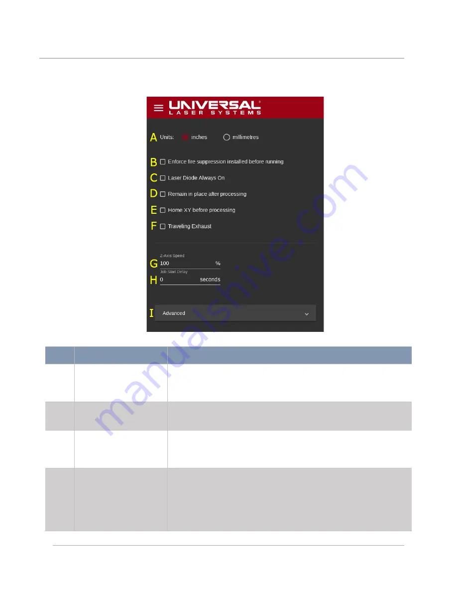
This page provides access to system-wide configuration options. 


FEATURE


DESCRIPTION


Units Selection Radio 

Buttons 

Enables users to select the measurement units to be used 

throughout the LSM by selecting one of two radio buttons: inches 

and millimeters. 

Enforce Fire 

Suppression Checkbox 

Forces the system to check for the presence of a fully pressurized 

fire suppression module each time laser processing is initiated. 

Laser Diode Always On 

Checkbox 

Keeps the laser diode on while the system is powered on. If 

unchecked, the diode will only illuminate when the system is 

powered on and the top door is opened. 

Remain in Place After 

Processing Checkbox 

Overrides the default carriage position. After laser processing  

has ended, the carriage defaults to the upper left-hand corner  

of the processing area to facilitate user access to the processing 

area. Checking this box keeps the system in place after  

processing ceases. 

Содержание ULTRA X6000

Страница 1: ...ULTRA X6000 Laser System User Guide www ulsinc com Version 2020 06 0102...

Страница 2: ...a 81 45 224 2270 Japan Again thank you for choosing ULS Sincerely Universal Laser Systems 2020 Universal Laser Systems All Rights Reserved Universal Laser Systems Inc name and logo are registered trad...

Страница 3: ...Table of Contents 1 ULTRA X6000 Platform Overview 5 2 Safety 13 3 Meet the ULTRA X6000 Platform 27 4 Laser System Manager LSM Overview 33 5 The ULTRA X6000 Workflow 77 6 Maintaining the Laser System 8...

Страница 4: ...4 This page left intentionally blank...

Страница 5: ...with a thickness up to 12 in 305 mm and may be configured with up to three laser sources When the ULTRA X6000 Platform is configured with two interchangeable CO2 lasers and one fiber laser users may t...

Страница 6: ...d 1 1 06 m OR 2 10 6 m and 1 1 06 m OR 2 9 3 m and 1 1 06 m OR 1 10 6 m and 1 9 3 m and 1 1 06 m Maximum Laser Power CO2 150W Fiber 50W Rapid Reconfiguration CO2 Laser Sources only Patented technology...

Страница 7: ...encoders Intelligent Path Planner Comprehensive path planning algorithm that minimizes laser processing completion time Multifunction Material Support Structure A built in aluminum honeycomb work surf...

Страница 8: ...ocessing byproducts monitors filtration performance at every stage and alerts the operator when predefined contaminant thresholds have been reached Connects directly with the laser system to turn filt...

Страница 9: ...hile the laser system is in use exposure to the laser beam may cause combustible materials to ignite which may lead to a fire System External Dimensions Width 63 09 in 1603 mm with Control Panel folde...

Страница 10: ...ation Control User control to define acceleration for vector motion for each control file Kerf Compensation Compensates for material width removed during laser cutting in order to achieve desired dime...

Страница 11: ...11 ULTRA X6000 Platform Dimensional Drawings ULTRA X6000 Platform Front View All dimensions are indicated in inches and millimeters...

Страница 12: ...12 ULTRA X6000 Platform Side View All dimensions are indicated in inches and millimeters...

Страница 13: ...fety information set out in this safety section before operating the equipment If you have any safety questions please email the ULS Support Team at support ulsinc com or call 1 480 609 0297 USA 43 1...

Страница 14: ...bels is not necessary during normal operation If it becomes necessary to open one of these enclosures the laser system must first be disconnected from the power source NEVER REMOVE THE GROUND LEAD TO...

Страница 15: ...ue tinted material is used in conjunction with the laminated safety glass to block both 10 6 and 9 3 m CO2 and 1 06 m fiber laser energy DO NOT OPERATE THE LASER SYSTEM IF THE VIEWING WINDOW IS DAMAGE...

Страница 16: ...Optional Class 4 Pass Through Module is available to enable the user to operate the laser system with the side access panels open by bypassing their safety interlocks With this optional device in plac...

Страница 17: ...CLASS 4 SAFETY MEASURES THESE SAFETY MEASURES ARE THE RESPONSIBILITY OF THE OWNER AND ARE MANDATORY FOR OPERATION OF CLASS 4 LASER SYSTEMS UNDER FEDERAL AND STATE LAW IN THE UNITED STATES AS WELL AS...

Страница 18: ...ample anyone wishing to operate a Class 4 laser system must register with the state radiation regulatory agency pay annual fees and submit to annual inspections There may be penalties involved for non...

Страница 19: ...19 ULS CO2 Laser Source Safety Labels...

Страница 20: ...20 ULS Fiber Laser Source Safety Label...

Страница 21: ...21 ULTRA X6000 Platform Safety Labels Isometric Side View...

Страница 22: ...22 ULTRA X6000 Platform Safety Labels Rear View...

Страница 23: ...23 ULTRA X6000 Platform Safety Labels Left View...

Страница 24: ...24 Class 4 Pass Through Safety Labels...

Страница 25: ...1 65 EU ROHS2 Amended 2012 19 EU WEEE Directive Based on the standards listed Standards Used Safety EN 60950 1 2013 EN 60825 1 2014 Class 2 EMC EN 61000 6 2 2019 EN 61000 6 4 2007 Class A EN 61000 3 2...

Страница 26: ...se Users should be aware that changes or modifications to this equipment not expressly approved by the manufacturer may void the user s authority to operate the equipment This equipment has been type...

Страница 27: ...27 Meet the ULTRA X6000 Platform 3...

Страница 28: ...des operational controls D Emergency Stop E Stop Instantly de energizes the system when depressed USE THIS BUTTON IN CASE OF EMERGENCY ONLY To reset the system after executing an E Stop twist the red...

Страница 29: ...provides through table vacuum hold down There are two varieties of this table motorized adjustment with 12 in 305 mm of travel and manual adjustment with 3 in 75 mm of travel I Front Door Lock Holds t...

Страница 30: ...meaning the laser system will not fire while it is opened D Bottom Laser Cover Covers the bottom portion of the CO2 Laser Sources This cover is interlocked meaning the laser system will not fire whil...

Страница 31: ...port that communicates with laser system accessories such as the optional ULS Air Compressor the optional UAC 2000 4000 and the optional Vacuum Booster H Accessory Connection Point 2 RJ11 port that co...

Страница 32: ...32 This page left blank intentionally...

Страница 33: ...following Quick Reference Guide provides a brief overview of the functionality of the LSM Main Menu The Main Menu of the LSM is accessible by pressing the Main Menu Button three horizontal lines in th...

Страница 34: ...Opens the User Details Page where a currently logged in user may change their passwords and view their operational permissions H User Management Page Opens the User Management Page where users may be...

Страница 35: ...of this manual B Focus View Opens the Focus View as the current menu on the right hand side of the LSM For further details refer to the Focus View section of this manual C Relocation View Opens the Re...

Страница 36: ...e Design File Preview Units are adjustable in the Systems Configuration Page I Horizontal Rule Provides a vertical position reference in the processing area for the Design File Preview Units are adjus...

Страница 37: ...ms with a fixed Z Axis left and a motorized Z Axis right FEATURE DESCRIPTION A Begin Processing Button Initiates laser material processing during which time the button will be disabled B C Axis Joysti...

Страница 38: ...arrow buttons between Low Medium and High on each joystick The current sensitivity level is indicated by the number of chevrons on the button More chevrons indicate larger movement distances I System...

Страница 39: ...ablish the home position Note that this procedure may take up to one minute to complete P Z Axis Joystick Moves the material support structure Z Axis up and down Touch and drag the central button to m...

Страница 40: ...at the active anchor becomes coincident with the carriage location D Anchor to Location Dialog Button Moves the active anchor to the specified X and Y locations Units are adjustable in the Systems Con...

Страница 41: ...file Duplicates will be placed to the right and below the location of the current design file To maximize the number of instances place the original design file in the upper left hand corner of the p...

Страница 42: ...gap settings Units are adjustable in the Systems Configuration Page D Duplicate to Fill Button Generates duplications to fill the field rightwards and downwards from the location of the original desig...

Страница 43: ...ew Area Shows the current view of the camera onboard the carriage B Camera Crosshair Indicates the centerlines of the camera This is primarily used for camera registration purposes C Contrast Adjustme...

Страница 44: ...Opens the Create a New Recipe Wizard enabling the creation of a recipe from the current processing settings These settings can be later recalled and applied to another control file C Select a Recipe...

Страница 45: ...l processes with their assigned colors Processes will be executed from top to bottom Colors within the same process will be executed from left to right J Process Edit Buttons Opens the associated proc...

Страница 46: ...perSpeed attachment can be used Selecting this option will more than double the throughput of raster processes C Image Density Selects image density Higher numbers will result in more raster passes pe...

Страница 47: ...ach raster stroke the same length over the entire process the length of the widest single raster line G Margin Amount Specifies the amount of additional motion system travel beyond the right and left...

Страница 48: ...deviation from sharp corners allowed when vector processing Smaller values will be more faithful to the original design file while larger settings will increase throughput Setting even a small value...

Страница 49: ...wn above this description will appear in the Process Settings Tab with any recipe information that may be saved C Skip Process Toggle Button Provides an easy way to store the process settings while en...

Страница 50: ...Gas Assist is desired the Coaxial or Lateral Gas Assist attachment must be removed and no process can be selected to use either Gas or Air I Gas Assist Flow Rate Enables target flow rate adjustment f...

Страница 51: ...that may be saved C Skip Process Toggle Button Provides an easy way to store the process settings while enabling the user to quickly disable a selected process If toggled on the selected process will...

Страница 52: ...ign file of the selected process that are completely closed Kerf compensation will not be applied to shapes that are open even by a small amount K Repeat Count The number of times to repeat a selected...

Страница 53: ...this description will appear in the Process Settings Tab along with any recipe information that may be saved C Skip Process Toggle Button Provides an easy way to store the process settings while enab...

Страница 54: ...ment must be removed and no process can be set to use either Gas or Air I Gas Assist Flow Rate Enables target flow rate adjustment for the Gas Assist source This option is not available when None is s...

Страница 55: ...ppearing in the text box shown above this description will also appear in the Process Settings Tab along with any recipe information that may be saved C Skip Process Toggle Button Provides an easy way...

Страница 56: ...h for the selected process J Kerf Width Enables Kerf Compensation which allows users to compensate for the width of a cut or mark when the value is set to any non zero value Note that Kerf Compensatio...

Страница 57: ...ption will also appear in the Process Settings Tab along with any recipe information that may be saved C Skip Process Toggle Button Provides an easy way to store the process settings while enabling th...

Страница 58: ...o use either Gas or Air H Gas Assist Flow Rate Enables target flow rate adjustment for the Gas Assist source This option is not available when None is selected for Gas Assist I Repeat Count The number...

Страница 59: ...user to quickly disable a selected process If toggled on the process will be greyed out in the Process Settings Tab indicating that it will currently be skipped when the system processes the selected...

Страница 60: ...y way to store process settings while enabling the user to quickly disable a selected process If toggled on the process will be greyed out in the Process Settings Tab indicating that it will currently...

Страница 61: ...ailable when None is selected for Gas Assist H Number of Drill Pulses Indicates the number of drill pulses to be dispensed I Duty Cycle The percent of time the laser remains on for each pierce pulse J...

Страница 62: ...nged by selecting the control file and renaming it in the processing settings D Export Control File Button Exports the control file to either the local drive or to a USB flash drive This feature is us...

Страница 63: ...re and apply settings for commonly used setups and materials FEATURE DESCRIPTION A Recipe ID Displays a unique identifier for each recipe that is automatically assigned when the recipe is created B Re...

Страница 64: ...ressurized fire suppression module each time laser processing is initiated C Laser Diode Always On Checkbox Keeps the laser diode on while the system is powered on If unchecked the diode will only ill...

Страница 65: ...l adjusts motion system performance to accommodate the extra weight of the traveling exhaust G Z Axis Speed Controls the maximum speed of the Z Axis enabling the value to be reduced below the standard...

Страница 66: ...uently FEATURE DESCRIPTION A Alignment Calibration Launches the Alignment Calibration Dialog B Camera Calibration Launches the Camera Calibration Wizard C Table Level Calibration Launches the Table Le...

Страница 67: ...o the hardware port of the device with which the LSM will communicate Connections may be accessed under the top laser cover on the back of the laser system B Output Trigger Defines the output event to...

Страница 68: ...e currently logged in user B Logout Button Logs the current user out of the system C Change Password Button Enables the current user to change the password associated with their account D Current User...

Страница 69: ...the current Emission Status of the laser system If a laser source could potentially start firing the indicator is shown as it is above If any of the interlocks are opened for example if the top or fro...

Страница 70: ...m B Add User Button Creates a new user C User Names Lists users who are authorized to operate the laser system D User Privileges Drop Down Displays the permissions each user has been granted E Delete...

Страница 71: ...tion FEATURE DESCRIPTION A Network Name of the System Gives the system a name for easy identification on attached networks B Wireless Network Enable Toggle Button Enables or disables the wireless netw...

Страница 72: ...Address The network address of the system on the Wired Network G IPv4 IPv6 Labels Read only labels for the Wireless Network H Wireless Network Connection Type Read only information regarding the Wire...

Страница 73: ...c purposes FEATURE DESCRIPTION A Feedback Message Field Provides a field for the user to enter a message to be left in the log file B Record Feedback Button Saves a message typed into the Feedback Mes...

Страница 74: ...r system C Restore Recipes Restores a selected set of recipes to the system D Update Software Opens the Software Update Dialog Page E View Log Opens the System Log F Remote Diagnostics Launches a Remo...

Страница 75: ...session that gives a ULS Service Technician remote access to the laser system for troubleshooting purposes B Session Code Grants remote access of a user s laser system to a ULS Service Technician C Y...

Страница 76: ...e versions This list is pulled from ULS Servers and therefore requires an internet connection to operate properly C Install Button Begins the installation process for the selected version of software...

Страница 77: ...ANAGER The software that runs the ULTRA X6000 Laser System is the Laser System Manager LSM It handles all aspects of importing planning arranging organizing and running design files to completion Desi...

Страница 78: ...vector data ULTRA X6000 laser systems use these raster and vector elements to modify materials using either of two modes a raster mode or a vector mode RASTER MODE OF OPERATION The raster mode of oper...

Страница 79: ...ser cutting laser marking laser engraving laser surface modification etc DEFAULT PROCESSES When a new design file is imported into the LSM a material thickness and type must be selected from the ULS I...

Страница 80: ...RA X6000 laser system automatically focuses the system using a high accuracy touch probe that is configurable on a per process basis Alternatively the user may perform the focusing operation any time...

Страница 81: ...rsonal hygiene cotton swabs Lens cleaner supplied Vacuum cleaner with a soft bristle brush attachment Set of Allen wrenches sized from 0 050 12 7 mm to 3 16 4 7625 mm Suggested Routine Maintenance Sch...

Страница 82: ...ry Remove and clean the inside of the exhaust plenum Regularly inspect and clean your exhaust ducting to the laser system consult with HVAC professional Every 12 months Remove upper left external side...

Страница 83: ......

Отзывы: