


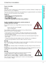


27
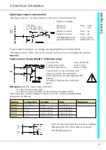
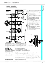
3 Electrical Installation
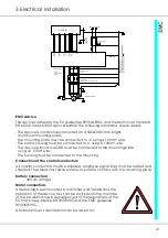
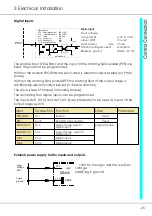
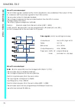
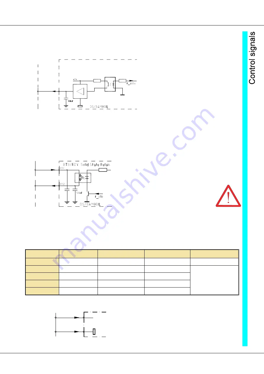
Digital logic outputs (open emitter)
The logic outputs 1 to 3 are rated for 24V and 1A (short-time: 2A)
Output voltage
On-level
max. +24V
Off-level
<1V
Output current
nom. 1A
Output current
max. 2A
Voltage reference
+24V (X1:4)
ground reference
GNDE(X1:10)
It is possible to program an energy saving program (clocked output).
The logic output 4 (24V, 3A) at the power section is only available with certain
devices.
Signal contact “Ready BTB/RDY” (Solid state relay)
Contact for
max. 48V/0.2A
Capacitive load
max. 1myF
Contact resistance
max. 2 Ohm
The contact is closed when the
device is ready for operation.
State signal via seven-segment LED
display.
In case of failures the contact is
open.
BTB opens
(red LED, open relay contact)
in case of error messages
in case of under-voltage of the auxiliary voltage (<20V)
The message “under-voltage in the bus circuit” can be programmed
(see Manual NDrive)
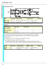
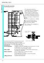
+24V for the logic and the auxiliary voltage
Observe the sum of all output currents!
GNDE logic ground
Digital
output
24V/1A
Digital outputs:
X1:13 dig.output 1
DOUT1
X1:14 dig.output 2
DOUT2
X1:17 dig.output 3
DOUT3
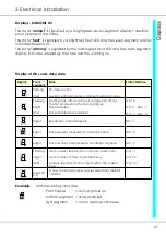
Safety
circuit
Output
Connection
Function
State
Parameter
BTB/RDY
X1:1, X1:2
Ready
fixed /Relay
DOUT1
X1:13
Digital output1
programmable
DOUT2
X1:14
Digital output2
programmable
DOUT3
X1:14
Digital output3
programmable
DOUT4
Xx:xx
Digital output4
programmable
Logic
voltage
24V=
Logic
ground
GNDE
DS400
+24V
X1:4
X1:10
Содержание Bamobil D3.2
Страница 3: ...1 Basic Information 3...
Страница 16: ...16 BAMOBIL D3 2...
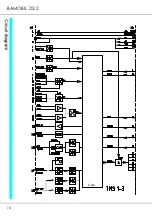
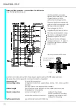
Страница 18: ...18 BAMOBIL D3 2 Core REFERENCE...
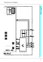
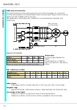
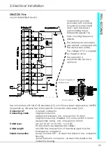
Страница 19: ...19 3 Electrical Installation Mains module Output stage 6x op coup driver...