


10
BAMO A1, A2 60-500A
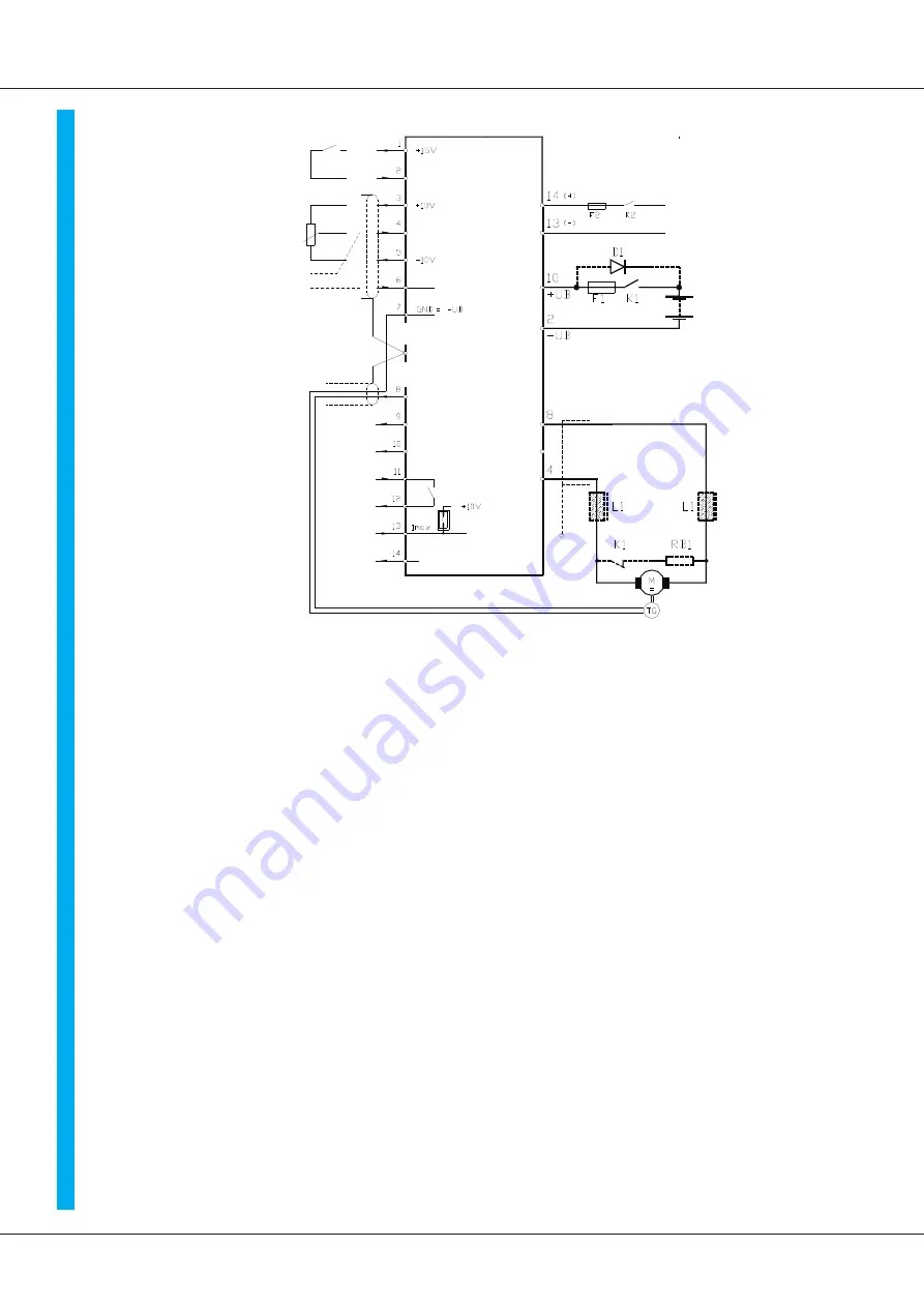
EnableEnable
Comm.value
potentiometer
PLC-
comm.value
Case
Comm.value±
Speed-act.value
Current-act.value
Current-comm.value
S1 contact 1
BTB
BTB
signal
Current limit
external
Overload-
signal
T
ER
MI
N
AL
X3
Enable
Comm.value ±
Battery voltage
Motor connection
Case
Auxiliary voltage 24V=
X2:
X1:
BAMO A1, A2
Notice:
Power connection X3:2 (-UB) , X3:10 (+UB)
Connection polarity >
no protection against mixing up the contacts
when the connection is wrong the output stage can be
distroyed!
The power connection must not be devided during braking! If nessesary built in
reverse-current-protection-diode D1. On-stage current = device peek current
Connection to Direct voltage bus or Power supply unit
Make sure that the overvoltage in the buffer circuit is limitated to 20% during braking.
Small resistance of the source or ballast circuit.
If the resistance of the motor is very small the fast rising of the buffer voltage circuit can
demage the semi-conductors. In normal case the device is switched to error by the
overvoltage observation.
Auxiliary voltage connection X3:13, X3:14
Safe against mixing up the contacts. The connection can be switched seperated
from the power connection.
Notice the tolerance and the residual ripple of the voltage.
Motor connection X3:4 (M1),X3:8 (M3)
The motor connections can be exchanged.
In case of EMC-problems use chokes and shielded line.
Brakong resistor RB1 and DC-contactor K1 as resistor brake with type A1 or as battery
failure brake with type A2
Control connections see special advices.
C
o
n
n
e
cti
o
n
o
ve
rv
ie
w


