


26
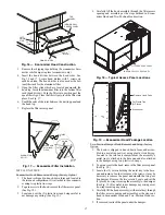
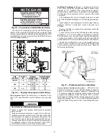
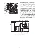
enclosure located under the main control box. The manual
switch handle is accessible through an opening in the access
panel. Discard the factory test leads (see Fig. 43). The factory
disconnect is an 80A disconnect.
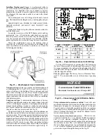
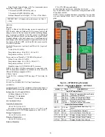
Fig. 43 — Power Wiring Connections
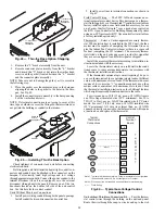
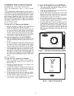
Convenience Outlets
Two types of convenience outlets are offered on the 50TC-
D16:
non-powered and unit-powered. Both types provide a
125-volt GFCI (ground-fault circuit-interrupter) duplex recep-
tacle rated at 15-A behind a hinged waterproof access cover,
located on the panel beneath the control box. See Fig. 44.
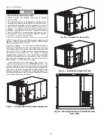
Fig. 44 — Convenience Outlet Location
Non-powered type:
This type requires the field installation of
a general-purpose 125-volt 15-A circuit powered from a
source elsewhere in the building. Observe national and local
codes when selecting wire size and conduit requirements, fuse
or breaker requirements and disconnect switch size and loca-
tion. Route 125-v power supply conductors into the bottom of
the utility box containing the duplex receptacle.
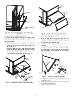
Unit-powered type:
A unit-mounted transformer is factory-
installed to stepdown the main power supply voltage to the unit
to 115-v at the duplex receptacle. This option also includes a
manual switch with fuse, located in a utility box and mounted
on a bracket behind the convenience outlet; access is through
the panel beneath the control box. See Fig. 44.
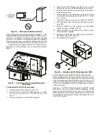
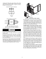
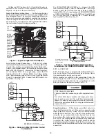
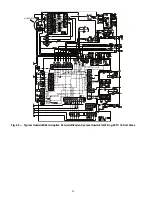
The primary leads to the convenience outlet transformer are
not factory-connected. Selection of primary power source is a
customer-option. If local codes permit, the transformer primary
leads can be connected at the line-side terminals on the unit-
mounted non-fused disconnect switch; this will provide service
power to the unit when the unit disconnect switch is open.
Other connection methods will result in the convenience outlet
circuit being de-energized when the unit disconnect switch is
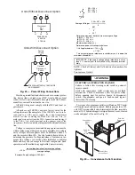
open. See Fig. 46. On a unit without a unit-mounted discon-
nect, connect the source leads to the main terminal block
(TB1).
If the convenience outlet transformer is connected to the line
side of a field disconnect, the conduit provided with the unit
must be used to protect the wire as they are routed from the
transformer to the field disconnect. The end of the conduit with
the straight connector attaches to the field disconnect. The
other end does not need to connect to the transformer; how-
ever, the conduit must be routed so that all wiring is either in
the conduit or behind the access panel.
If the convenience outlet transformer is connected to the line
side of the factory disconnect option, route the wires through
the web bushing located on the bottom of the disconnect box.
For the load side wiring to the factory option disconnect, route
the wires through the hole on the right side of the disconnect.
Be sure to create a drip loop at least 6 in. long.
WARNING
ELECTRICAL OPERATION HAZARD
Failure to follow this warning could result in personal
injury or death.
Units with convenience outlet circuits may use multiple
disconnects. Check convenience outlet for power status
before opening unit for service. Locate its disconnect
switch, if appropriate, and open it. Lock-out and tag-out
this switch, if necessary.
Units Without Disconnect Option
Units With Disconnect Option
2
4
6
1
3
5
L1
L2
L3
Optional
Disconnect
Switch
Disconnect factory test leads; discard.
Factory
Wiring
11
12
13
L1
L2
L3
TB1
208/230-3-60
460-3-60
575-3-60
Disconnect
per
NEC
Convenience
Outlet
GFCI
Pwd-CO
Fuse
Switch
Pwd-CO
Transformer
Disconnect
Access Panel
Содержание Carrier WeatherMaker 50TC A08 Series
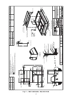
Страница 4: ...4 Fig 2 Unit Dimensional Drawing Size 08 09 12 Units...
Страница 5: ...5 Fig 2 Unit Dimensional Drawing Size 08 09 12 Units cont...
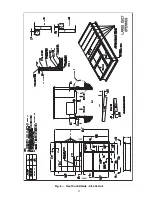
Страница 6: ...6 Fig 3 Unit Dimensional Drawing Size 14 Unit...
Страница 7: ...7 Fig 3 Unit Dimensional Drawing Size 14 Unit cont...
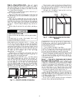
Страница 9: ...9 Fig 4 Unit Dimensional Drawing Size 16 Unit cont...
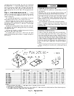
Страница 13: ...13 Fig 8 Roof Curb Details Size 16 Unit...
Страница 33: ...33 Fig 62 Typical Humidi MiZer Adaptive Dehumidification System Humidistat Wiring 50TC 08 14 Unit Sizes...
Страница 34: ...34 Fig 63 Typical Humidi MiZer Adaptive Dehumidification System Humidistat Wiring 50TC 16 Unit Sizes HUMIDISTAT...
Страница 50: ...50 Fig 73 50TC 16 Control Box Component PremierLink Locations...
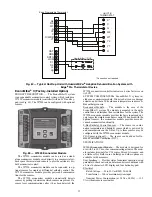
Страница 51: ...51 Fig 74 Typical PremierLink Control Wiring Diagram...
Страница 52: ...52 Fig 75 Typical PremierLink Control Wiring Diagram with Humidi MiZer System Option...
Страница 64: ...64 Fig 106 Typical RTU Open Controller Wiring Diagram 50TC 08 14 Size Units...
Страница 65: ...65 Fig 107 Typical RTU Open Controller Wiring Diagram 50TC 16 Size Unit...
Страница 66: ...66 Fig 108 Typical RTU Open Controller Wiring Diagram with Humidi MiZer System Option 50TC 08 14 Size Units...
Страница 67: ...67 Fig 109 Typical RTU Open Controller Wiring Diagram with Humidi MiZer System Option 50TC 16 Size Units...


