2
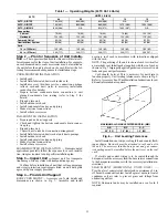
Rated Indoor Airflow (cfm) —
The table below lists
the rated indoor airflow used for the AHRI efficiency rating for
the units covered in this document.
Pre-Installation —
Complete the following checks be-
fore installation.
1. Consult local building codes and the NEC (National
Electrical Code) ANSI/NFPA 70 for special installa-
tion requirements.
2. Determine unit location (from project plans) or select unit
location.
Check for possible overhead obstructions which may inter-
fere with unit lifting or rigging.
WARNING
ELECTRICAL SHOCK HAZARD
Failure to follow this warning could cause personal injury
or death.
Before performing service or maintenance operations on
unit, always turn off main power switch to unit and install
lock(s) and lockout tag(s). Unit may have more than one
power switch.
WARNING
UNIT OPERATION AND SAFETY HAZARD
Failure to follow this warning could cause personal injury,
death and/or equipment damage.
Puron
®
(R-410A) refrigerant systems operate at higher
pressures than standard R-22 systems. Do not use R-22 ser-
vice equipment or components on Puron refrigerant equip-
ment.
WARNING
PERSONAL INJURY AND ENVIRONMENTAL
HAZARD
Failure to follow this warning could cause personal injury
or death.
Relieve pressure and recover all refrigerant before system
repair or final unit disposal.
Wear safety glasses and gloves when handling refrigerants.
Keep torches and other ignition sources away from refrig-
erants and oils.
CAUTION
CUT HAZARD
Failure to follow this caution may result in personal injury.
Sheet metal parts may have sharp edges or burrs. Use care
and wear appropriate protective clothing, safety glasses and
gloves when handling parts and servicing air-conditioning
equipment.
MODEL NUMBER
FULL LOAD AIRFLOW
(CFM)
50TC*A08
2400
50TC*D/E08
2250
50TC*A09
3000
50TC*D/E09
3400
50TC*A12
3600
50TC*D/E12
3000
50TC*D/E14
3600
50TC*D16
5250
Содержание Carrier WeatherMaker 50TC A08 Series
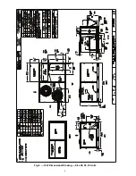
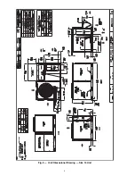
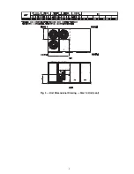
Страница 4: ...4 Fig 2 Unit Dimensional Drawing Size 08 09 12 Units...
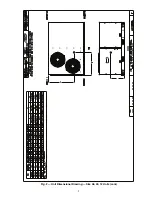
Страница 5: ...5 Fig 2 Unit Dimensional Drawing Size 08 09 12 Units cont...
Страница 6: ...6 Fig 3 Unit Dimensional Drawing Size 14 Unit...
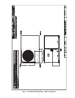
Страница 7: ...7 Fig 3 Unit Dimensional Drawing Size 14 Unit cont...
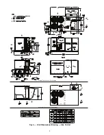
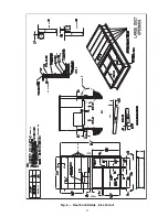
Страница 9: ...9 Fig 4 Unit Dimensional Drawing Size 16 Unit cont...
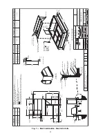
Страница 13: ...13 Fig 8 Roof Curb Details Size 16 Unit...
Страница 33: ...33 Fig 62 Typical Humidi MiZer Adaptive Dehumidification System Humidistat Wiring 50TC 08 14 Unit Sizes...
Страница 34: ...34 Fig 63 Typical Humidi MiZer Adaptive Dehumidification System Humidistat Wiring 50TC 16 Unit Sizes HUMIDISTAT...
Страница 50: ...50 Fig 73 50TC 16 Control Box Component PremierLink Locations...
Страница 51: ...51 Fig 74 Typical PremierLink Control Wiring Diagram...
Страница 52: ...52 Fig 75 Typical PremierLink Control Wiring Diagram with Humidi MiZer System Option...
Страница 64: ...64 Fig 106 Typical RTU Open Controller Wiring Diagram 50TC 08 14 Size Units...
Страница 65: ...65 Fig 107 Typical RTU Open Controller Wiring Diagram 50TC 16 Size Unit...
Страница 66: ...66 Fig 108 Typical RTU Open Controller Wiring Diagram with Humidi MiZer System Option 50TC 08 14 Size Units...
Страница 67: ...67 Fig 109 Typical RTU Open Controller Wiring Diagram with Humidi MiZer System Option 50TC 16 Size Units...

