


40
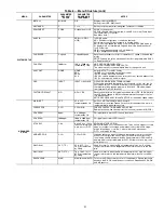
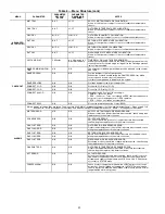
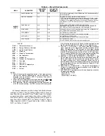
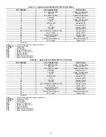
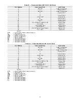
Table 6 — Menu Structure (cont)
MENU
PARAMETER
PARAMETER
DEFAULT
VALUE
PARAMETER
RANGE AND
INCREMENT
NOTES
STATUS (CONT)
ACT COUNT
N/A
1 to 65535
Displays number of times actuator has cycled.
1 cycles equals 180 deg. of actuator movement in any direction.
ACTUATOR
N/A
OK/Alarm (on Alarm
menu)
Displays ERROR if voltage or torque is below actuator range.
EXH1 OUT
OFF
ON/OFF
EXHAUST STAGE 1 RELAY OUTPUT
Output of EXH1 terminal:
ON = relay closed
OFF = relay open
EXH2 OUT
OFF
ON/OFF
EXHAUST STAGE 2 RELAY OUTPUT
Output of AUX terminal; displays only if AUX = EXH2
ERV
OFF
ON/OFF
ENERGY RECOVERY VENTILATOR
Output of AUX terminal; displays only if AUX = ERV
MECH COOL ON
or
HEAT STAGES ON
0
0, 1, or 2
Displays stage of mechanical cooling that is active.
Displays the stage of heat pump heating that is active.
FAN SPEED
N/A
LOW or HIGH
SUPPLY FAN SPEED
Displays speed setting of fan on a 2-speed fan unit.
W (HEAT ON)
N/A
ON/OFF
HEAT DEMAND STATUS
Displays status of heat demand on a 2-speed fan unit.
SETPOINTS
MAT SET
53F
38 to 65 F; increment
by 1
SUPPLY AIR SETPOINT
Setpoint determines where the economizer will modulate the OA
damper to maintain the mixed air temperature.
LOW T LOCK
32F
-45 to 80 F;
increment by 1
COMPRESSOR LOW TEMPERATURE LOCKOUT
Setpoint determines outdoor temperature when the mechanical cooling
cannot be turned on. Commonly referred to as the Compressor lockout.
DRYBLB SET
63F
48 to 80 F; increment
by 1
OA DRY BULB TEMPERATURE CHANGEOVER SETPOINT
Setpoint determines where the economizer will assume outdoor air tem-
perature is good for free cooling; e.g.; at 63 F unit will economize at 62 F
and below and not economize at 64 F and above. There is a 2 F dead-
band.
ENTH CURVE
ES3
ES1,ES2,ES3,ES4,
or ES5
ENTHALPY CHANGEOVER CURVE
Enthalpy boundary “curves” for economizing using single enthalpy.
DCV SET
1100ppm
500 to 2000ppm;
increment by 100
DEMAND CONTROLLED VENTILATION
Displays only if CO
2
sensor is connected. Setpoint for Demand Control
Ventilation of space. Above the setpoint, the OA dampers will modulate
open to bring in additional OA to maintain a space ppm level below the
setpoint.
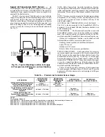
MIN POS
2.8 V
2 to 10 Vdc
VENTILATION MINIMUM POSITION
Displays ONLY if a CO
2
sensor is NOT connected.
VENTMAX
With 2-speed fan units
VENTMAX L (low speed fan)
and VENTMAX H (high
speed fan) settings are
required
2.8 V
2 to 10 Vdc
DCV MAXIMUM DAMPER POSITION
Displays only if a CO
2
sensor is connected. Used for Vbz (ventilation
max cfm) setpoint. Displays 2 to 10 V if <3 sensors (RA,OA, and MA). In
AUTO mode dampers controlled by CFM.
100 to 9990 cfm;
increment
by 10
If OA, MA, RA, and CO
2
sensors are connected and DCV CAL ENABLE
is set to AUTO mode, the OA dampers are controlled by CFM and dis-
plays from 100 to 9990 CFM.
2 to 10 Vdc
With 2-speed fan units VENT L (low speed fan) and MIN POS H (high
speed fan) settings are required. Default for VENTMAX L is 3.2V and
VENTMAX H is 2.8V
VENTMIN
With 2-speed
fan units VENTMIN L (low
speed fan) and VENTMIN
H (high speed fan) set
2.25 V
2 to 10 Vdc or 100 to
9990 cfm increment
by 10
DCV MINIMUM DAMPER POSITION
Displays only if a CO
2
sensor is connected. Used for Ba (ventilation min
cfm) setpoint. Displays 2 to 10 V if <3 sensors (RA, OA, and MA). Va is
only set if DCV is used. This is the ventilation for less than maximum
occupancy of the space. In AUTO mode dampers controlled by CFM.
100 to 9990 cfm;
increment
by 10
If OA, MA, RA, and CO
2
sensors are connected and DCV CAL ENABLE
is set to AUTO mode, the OA dampers are controlled by CFM and dis-
plays from 100 to 9990 CFM.
2 to 10 Vdc
With 2-speed fan units VENTMIN L (low speed fan) and MIN POS H
(high speed fan) settings are required. Default for VENTMIN L is 3.2V
and VENTMIN H is 2.8V
ERV OAT SP
32°F
0 to 50 F; increment
by 1
ENERGY RECOVERY VENTILATOR UNIT OUTDOOR AIR TEM-
PERATURE SETPOINT
Only when AUX1 O = ERV
EXH1 SET
With 2-speed fan units Exh1
L (low speed fan) and Exh1
H (high speed fan) settings
are required
50%
0 to 100%;increment
by 1
EXHAUST FAN STAGE 1 SETPOINT
Setpoint for OA damper position when exhaust fan 1 is powered by the
economizer.
With 2-speed fan units Exh1 L (low speed fan) and Exh1 H (high speed
fan) settings are required. Default for Exh1 L is 65% and Exh1 H is 50%
EXH2 SET
With 2-speed fan units Exh2
L (low speed fan) and Exh2
H (high speed fan) settings
are required
75%
0 to 100%; increment
by 1
EXHAUST FAN STAGE 2 SETPOINT
Setpoint for OA damper position when exhaust fan 2 is powered by the
economizer. Only used when AUX1 O is set to EHX2.
With 2-speed fan units Exh2 L (low speed fan) and Exh2 H (high speed
fan) settings are required. Default for Exh2 L is 80% and Exh2 H is 75%
Содержание Carrier WeatherMaker 50TC A08 Series
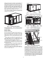
Страница 4: ...4 Fig 2 Unit Dimensional Drawing Size 08 09 12 Units...
Страница 5: ...5 Fig 2 Unit Dimensional Drawing Size 08 09 12 Units cont...
Страница 6: ...6 Fig 3 Unit Dimensional Drawing Size 14 Unit...
Страница 7: ...7 Fig 3 Unit Dimensional Drawing Size 14 Unit cont...
Страница 9: ...9 Fig 4 Unit Dimensional Drawing Size 16 Unit cont...
Страница 13: ...13 Fig 8 Roof Curb Details Size 16 Unit...
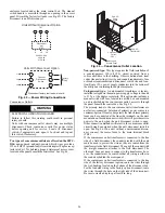
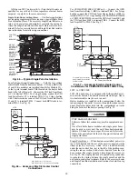
Страница 33: ...33 Fig 62 Typical Humidi MiZer Adaptive Dehumidification System Humidistat Wiring 50TC 08 14 Unit Sizes...
Страница 34: ...34 Fig 63 Typical Humidi MiZer Adaptive Dehumidification System Humidistat Wiring 50TC 16 Unit Sizes HUMIDISTAT...
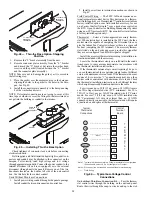
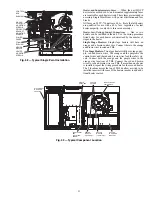
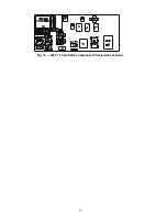
Страница 50: ...50 Fig 73 50TC 16 Control Box Component PremierLink Locations...
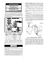
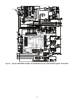
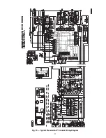
Страница 51: ...51 Fig 74 Typical PremierLink Control Wiring Diagram...
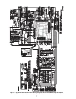
Страница 52: ...52 Fig 75 Typical PremierLink Control Wiring Diagram with Humidi MiZer System Option...
Страница 64: ...64 Fig 106 Typical RTU Open Controller Wiring Diagram 50TC 08 14 Size Units...
Страница 65: ...65 Fig 107 Typical RTU Open Controller Wiring Diagram 50TC 16 Size Unit...
Страница 66: ...66 Fig 108 Typical RTU Open Controller Wiring Diagram with Humidi MiZer System Option 50TC 08 14 Size Units...
Страница 67: ...67 Fig 109 Typical RTU Open Controller Wiring Diagram with Humidi MiZer System Option 50TC 16 Size Units...


