


27
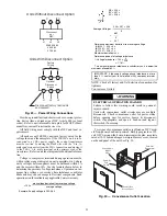
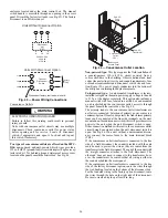
Fig. 45 — Convenience Outlet Utilization Notice
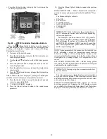
Test the GFCI receptacle by pressing the TEST button on
the face of the receptacle to trip and open the receptacle. Check
for proper grounding wires and power line phasing if the GFCI
receptacle does not trip as required. Press the RESET button to
clear the tripped condition.
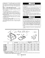
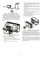
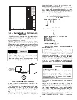
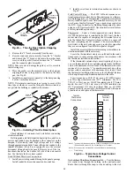
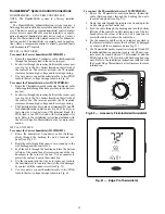
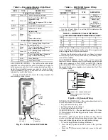
Fig. 46 — Powered Convenience Outlet Wiring
Fuse on power type:
The factory fuse is a Bussman “Fuse-
tron” T-15, non-renewable screw-in (Edison base) type plug
fuse.
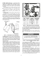
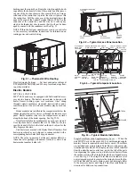
Installing Weatherproof Cover:
A weatherproof while-in-
use cover for the factory-installed convenience outlets is now
required by UL standards. This cover cannot be factory-
mounted due its depth; it must be installed at unit installation.
For shipment, the convenience outlet is covered with a blank
cover plate.
The weatherproof cover kit is shipped in the unit’s control
box. The kit includes the hinged cover, a backing plate and gas-
ket.
DISCONNECT ALL POWER TO UNIT AND CONVE-
NIENCE OUTLET. LOCK-OUT AND TAG-OUT ALL
POWER.
Remove the blank cover plate at the convenience outlet; dis-
card the blank cover.
Loosen the two screws at the GFCI duplex outlet, until ap-
proximately
1
/
2
-in. (13 mm) under screw heads are exposed.
Press the gasket over the screw heads. Slip the backing plate
over the screw heads at the keyhole slots and align with the
gasket; tighten the two screws until snug (do not over-tighten).
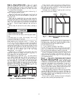
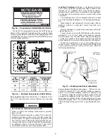
Mount the weatherproof cover to the backing plate as
shown in Fig. 47. Remove two slot fillers in the bottom of the
cover to permit service tool cords to exit the cover. Check for
full closing and latching.
Fig. 47 — Weatherproof Cover Installation
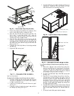
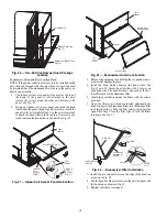
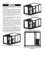
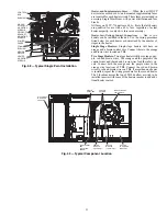
Factory Option Thru-Base Connections — This service con-
nection kit consists of a
1
/
2
-in. electrical bulkhead connector
and a 1
1
/
2
-in. electrical bulkhead connector, connected to an
“L” bracket covering the embossed (raised) section of the unit
basepan in the condenser section. See Fig. 48. The
1
/
2
-in. bulk-
head connector enables the low-voltage control wires to pass
through the basepan. The 1
1
/
2
-in. electrical bulkhead connector
allows the high-voltage power wires to pass through the base-
pan.
WARNING
ELECTRICAL OPERATION HAZARD
Failure to follow this warning could result in personal
injury or death.
Using unit-mounted convenience outlets: Units with unit-
mounted convenience outlet circuits will often require that
two disconnects be opened to de-energize all power to the
unit. Treat all units as electrically energized until the con-
venience outlet power is also checked and de-energization
is confirmed. Observe National Electrical Code Article
210, Branch Circuits, for use of convenience outlets.
2.0
50HE501288
NOTICE/AVIS
Convenience Outlet Utilization
Maximum Intermittent Use 15 - Amps
Maximum Continuous Use 8 - Amps
Observe a 50% limit on the circuit
Loading above 8 - Amps
Utilisation de la prise utilitaire
Usage intermittent maximum 15 - Amps
Usage continu maximum 8 - Amps
Observez une limite de 50% sur le circuit
Chargement au-dessus de 8 - Amps
UNIT
VOLTAGE
CONNECT
AS
PRIMARY
CONNECTIONS
TRANSFORMER
TERMINALS
208,230
240
L1: RED +YEL
L2: BLU + GRA
H1 + H3
H2 + H4
460
480
L1: RED
Splice BLU + YEL
L2: GRA
H1
H2 + H3
H4
575
600
L1: RED
L2: GRA
H1
H2
RECEPTACLE
NOT SHOWN
COVER – WHILE-IN-USE
WEATHERPROOF
BASE PLATE FOR
GFCI RECEPTACLE
Содержание Carrier WeatherMaker 50TC A08 Series
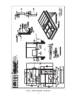
Страница 4: ...4 Fig 2 Unit Dimensional Drawing Size 08 09 12 Units...
Страница 5: ...5 Fig 2 Unit Dimensional Drawing Size 08 09 12 Units cont...
Страница 6: ...6 Fig 3 Unit Dimensional Drawing Size 14 Unit...
Страница 7: ...7 Fig 3 Unit Dimensional Drawing Size 14 Unit cont...
Страница 9: ...9 Fig 4 Unit Dimensional Drawing Size 16 Unit cont...
Страница 13: ...13 Fig 8 Roof Curb Details Size 16 Unit...
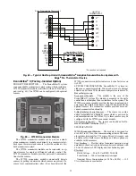
Страница 33: ...33 Fig 62 Typical Humidi MiZer Adaptive Dehumidification System Humidistat Wiring 50TC 08 14 Unit Sizes...
Страница 34: ...34 Fig 63 Typical Humidi MiZer Adaptive Dehumidification System Humidistat Wiring 50TC 16 Unit Sizes HUMIDISTAT...
Страница 50: ...50 Fig 73 50TC 16 Control Box Component PremierLink Locations...
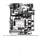
Страница 51: ...51 Fig 74 Typical PremierLink Control Wiring Diagram...
Страница 52: ...52 Fig 75 Typical PremierLink Control Wiring Diagram with Humidi MiZer System Option...
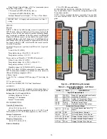
Страница 64: ...64 Fig 106 Typical RTU Open Controller Wiring Diagram 50TC 08 14 Size Units...
Страница 65: ...65 Fig 107 Typical RTU Open Controller Wiring Diagram 50TC 16 Size Unit...
Страница 66: ...66 Fig 108 Typical RTU Open Controller Wiring Diagram with Humidi MiZer System Option 50TC 08 14 Size Units...
Страница 67: ...67 Fig 109 Typical RTU Open Controller Wiring Diagram with Humidi MiZer System Option 50TC 16 Size Units...


