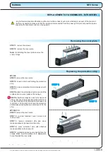
Replacing fixed bearing
STEP 1:
slide the carriage as close as possible to
the frontal end block and remove two set screws in
the bottom of the frontal end block, save the rubber
cylinders and reuse them in step 6.
STEP 2:
remove set screw and the bearing cover
from the rear end block and save the brass cylinder
(reuse it in step 6).
STEP 3:
slide the carriage towards the rear end
block together with the spindle, so that the fixed
bearing comes out of the rear end block.
STEP 4:
remove fixed bearing. Save the spacing
ring that lies between two bearings.
STEP 5:
mount new fixed bearing. Insert the
spacing ring between two bearings and make sure
that the bearings are turned correctly.
STEP 6:
assemble the module back together by:
- sliding the carriage towards frontal end block,
- inserting the fixed bearing cover (do not use glue),
- inserting the set screw that was removed from
frontal end block and one from rear end block.
Tighten set screw in the frontal end block to 1 Nm
and then loosen it for half a turn.
Replacing end blocks
Replacing the spindle, ball nut or the carriage
Note:
the
spindle and the ball nut must be replaced
at the same time as each nut is paired with specific
spindle.
STEP 1:
remove the spindle and the ball nut from
the module as described in previous chapters.
STEP 2:
slide the carriage from the module and
replace it with new one. Turn the carriage the same
way as was the old one. Take care that the balls do
not fall out of the rail-guide blocks (ignore this step if
you are not replacing carriage).
STEP 3:
insert the spindle with the ball nut into the
module and secure the ball nut to the carriage with
key and screw (do not remove nut from the
spindle)(if spacers were installed before and after
the nut make sure they are installed as well).
Note:
on MTV 80 spindle and nut are inserted from
other side than on MTV 65.
STEP 4:
mount the fixed bearing to the spindle as
described in “Replacing fixed bearing”.
STEP 5:
mount the leading profile and floating
bearing as described in “Replacing floating
bearing”.
STEP 6:
finish by mounting the frontal end block.
Align it with the profile of the module before
tightening the screws. Secure the floating bearing
with set screw in the side of the frontal end block.
MTV Series
MANUAL
1.090.0
M
A
Note:
all the screws (except set screws) must be glued (Loctite 243) and screwed
with the torque specified in the table on page 1.005.0 unless written otherwise at
the individual steps.
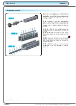
STEP 1
STEP 2
STEP 6
STEP 3
The specifications in order to improve the products in this catalogue are subject to change without notice.


