


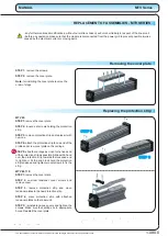


Removing spindle and nut from module
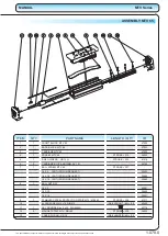
REPLACEMENT OF ASSEMBLIES - MTV SERIES
- any furthermentioned modifications, without our written consent, will void our liability in respect of the linear unit,
- before any operation make sure that the module is disconnected from the power grid to prevent possible injuries
caused by the electrical current or moving parts,
STEP 1:
remove the screws.
STEP 2:
remove the cover plate.
Note:
for installing the cover plate reverse the
order of steps.
Removing the cover plate
Replacing the protection strip
MTV 65:
STEP 1:
remove the cover plate.
STEP 2:
loosen set screws holding the protection
strip.
STEP 3:
remove protection strip and replace it with
new one.
STEP 4:
attach the protection strip to one end of the
profile and screw cover plate on the carriage.
STEP 5:
slide the carriage as close to the fixed end
of the protection strip as possible. Slide with a hand
over the protection strip towards the loosened end
to tighten it. At the end block hold the protection
strip tensioned and tighten two set screws to fix the
strip.
MTV 80, 110:
STEP 1:
remove the cover plate.
STEP 2:
unscrew tensioner cover screws and
remove cover.
STEP 3:
remove protection strip and move
tensioner plates to the new protection strip.
STEP 4:
place protection strip with attached
tensioner plates on the linear unit.
STEP 5:
reinstall tensione covers and tighten the
screws. Make sure that springs lie in appropriate
holes. Reinstall the cover plate.
Note:
all the screws (except set screws) must be glued (Loctite 243) and screwed
with the torque specified in the table on page 1.005.0 unless written otherwise at
the individual steps.
MTV Series
MANUAL
1.080.0
STEP 2
STEP 5
The specifications in order to improve the products in this catalogue are subject to change without notice.