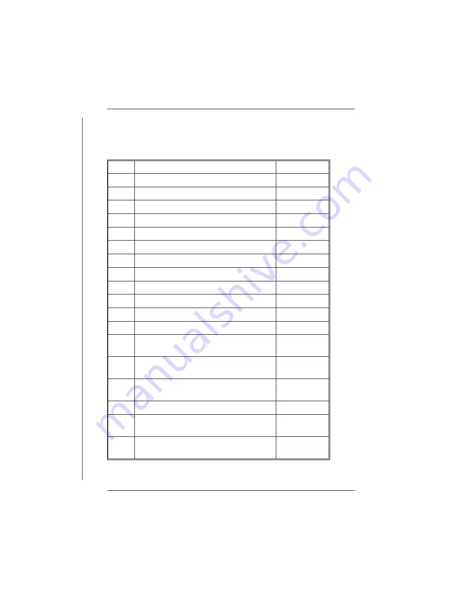
The following table lists each pin in the INPUT SIGNALS connector by
number. Next to the pin number is a description of the signal for which this
connection is designed. The last column lists the high resolution channel
mnemonic used by the STARLOG Software to refer to this connection.
Pin
Signal Description
Channel
1
Analog ground
2
Analog input
A1 (A1+ve)*
3
Analog input
A3 (A3+ve)
4
Analog input
A5 (A5+ve)
5
Analog input
A7 (A7+ve)
6
Analog input
A9 (A1-ve)
7
Analog input
A11 (A3-ve)
8
Analog input
A13 (A5-ve)
9
Analog input
A15 (A7-ve)
10
Sense input BIT 3 (Log Start, MASK 8)
SENSE 0
11
16 bit counter input (20kHz)
C0
12
16 bit counter input (20kHz)
C2
13
High Speed Synchronous Serial Port Clock
(TTL level input and output)
HSIO Clock 1
14
High Speed Synchronous Serial Port Clock
(TTL level input and output)
HSIO Clock 0
15
Control, Open collector output, 30V, 100mA
drive, 20ms pulse width
OUT 1
16
External power +12V (or recharge)
Power Input
17
+6V continuous power for external
instruments (1mA maximum)
Micro Power
18
Scan synchr5V regulated UPS or
HSIO Sync (@30mA max)
Sync Power or
HSIO Sync
UNIDATA
24 INSTALLATION & CONNECTION
Содержание Starlog Prologger 7001
Страница 1: ...STARLOG PROLOGGER Hardware Model 7001 Revision 33 Firmware User Manual Revision A 6261 May 1999...
Страница 6: ......
Страница 60: ......
Страница 64: ......
Страница 67: ...02 PROM Verify Fail 03 Mirror Fail 04 Bad checksum in RAM firmware PROLOGGER Hardware 3...
Страница 68: ......


