8.2
Hardware Register Information
The hardware register information can be viewed in Test Mode or used by
programmers wishing to write their own unload and analysis programs. The
table below gives a description of each register numbered 0 to 255. For
multiple byte registers the convention used is – least significant byte to most
significant byte. A byte may contain a number from 0 to 255 (8 bits) and for
calculating multiple byte numbers the first byte is added to the second byte
times 256 plus the third byte times 256 times 256, etc.
eg. The four byte number 1234 would give:
1+(2*256)+(3*256*256)+(4*256*256*256) = 67305985
Arithmetic instructions using 32-bit unsigned integers can represent values
from 0 to 4294967295.
8.2.1
PROLOGGER Memory Assignments
The PROLOGGER operating the standard instruction set, has the following
fixed memory assignments in the Hardware Register:
(Pin xx) refers to a pin of the INPUT SIGNALS connector.
Address Size
Description
0
1
Software Revision Number (33 onwards)
1
2
logger runtime in milliseconds (16 bit integer)
3
1
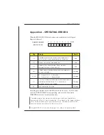
Error flags (see Appendix A)
4
4
logger scan counter (32 bit integer)
8
3
Reserved
11
2
MSB of address (bits 8-23) used in LDBLK and MVBLK
instructions
13
2
Reserved
14
2
Binary states of analog channels
16
8
Eight analog channels (a0 to a7) unsigned low resolution
representation (8 bit) of the 16 bit channel (A0 to A7) measurement
24
8
Counter channels
PROLOGGER Hardware
PROGRAMMING THE PROLOGGER 41
Содержание Starlog Prologger 7001
Страница 1: ...STARLOG PROLOGGER Hardware Model 7001 Revision 33 Firmware User Manual Revision A 6261 May 1999...
Страница 6: ......
Страница 60: ......
Страница 64: ......
Страница 67: ...02 PROM Verify Fail 03 Mirror Fail 04 Bad checksum in RAM firmware PROLOGGER Hardware 3...
Страница 68: ......


