9
PROLOGGER CONFIGURATION TABLE
The PROLOGGER has a number of operating modes for its analog inputs.
During factory calibration and testing a standard setup and some calibration
factors are permanently written into the logger’s firmware (in ROM). This
part of the firmware is referred to as the Configuration Table and a copy of it
is also located in protected memory. If a different configuration is required,
you may alter parts of the table.
This chapter describes the Configuration Table and its operation.
9.1
Default Configuration Table
The PROLOGGER has a permanent (default) copy of the Configuration
Table in a ROM (Read Only Memory) chip. This default version instructs the
logger to operate with commonly used settings. A user may alter some (or all)
of these default settings to instruct the logger in another manner.
PROLOGGER Hardware
PROLOGGER CONFIGURATION TABLE 47
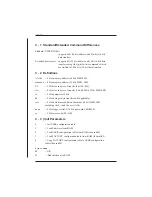
0
Hardware Registers
Buffer Control Table
Log Buffers
8192
Real Address
Virtual Address
Log Program
end of memory
256
384
0
Virtual Address is the
address used by the
LOG program and other
user communications.
Real Address
is the actual
hardware
protected
memory
memory address.
512k
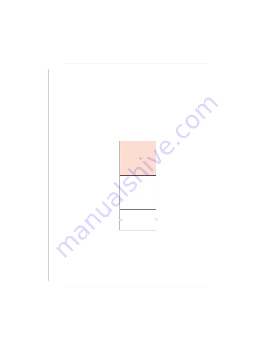
Memory Map of Real and Virtual Addresses.
Содержание Starlog Prologger 7001
Страница 1: ...STARLOG PROLOGGER Hardware Model 7001 Revision 33 Firmware User Manual Revision A 6261 May 1999...
Страница 6: ......
Страница 60: ......
Страница 64: ......
Страница 67: ...02 PROM Verify Fail 03 Mirror Fail 04 Bad checksum in RAM firmware PROLOGGER Hardware 3...
Страница 68: ......


