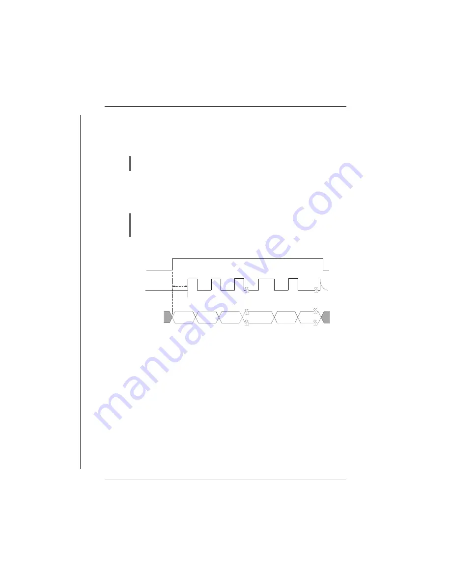
These ports are read each logger scan. The Sync signal (Pin 18) is used to
indicate to the remote equipment that a logger read scan is about to begin.
This signal is used to load the serial shift register(s) in the remote equipment
in preparation of being read.
The first data bit LSB must be present on the Data (0/1) signal within 7ms
after the Sync signal.
Serial transfer rate is 50 microseconds per bit with a 30 microsecond gap
between each byte. See the timing diagrams for Serial In and Serial Out
below.
Every 1mS a logger interrupt sequence adds a 50 microsecond delay to the
serial transfer sequence. Transfer starts with the least significant bit of the
least significant byte and each clock reads the next most significant bit.
PROLOGGER Hardware
INSTALLATION & CONNECTION 29
Pin 18
SYNC
Pin 14/13
CLOCK 0/1
Pin 32/31
DATA 0/1
LOGGER SCAN
20us
30us
Read Bit 0
Bit 1
Bit 2
50 us
10ms
Bit 0
Bit 1
Bit 2
Bit 7
0 (BYTE 1)
SERIAL IN
Bit 0
Bit 7
30us
Serial In Timing Diagram.
Содержание Starlog Prologger 7001
Страница 1: ...STARLOG PROLOGGER Hardware Model 7001 Revision 33 Firmware User Manual Revision A 6261 May 1999...
Страница 6: ......
Страница 60: ......
Страница 64: ......
Страница 67: ...02 PROM Verify Fail 03 Mirror Fail 04 Bad checksum in RAM firmware PROLOGGER Hardware 3...
Страница 68: ......


