


MD40
PRODUCT INSTRUCTION MANUAL
MD40
Page 13 of 56
Author: N.Carapiet | Revision: 1.1
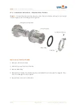
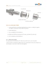
2.2.2 Installation instructions
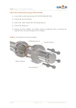
STAGE 1
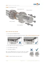
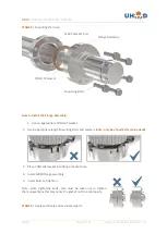
| The motor assembly and drive thimble will need to be removed in order to gain access
to the flange bolt holes.
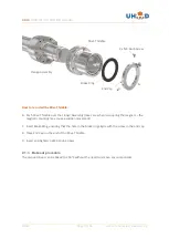
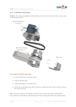
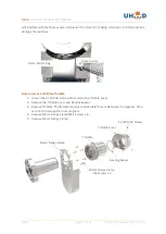
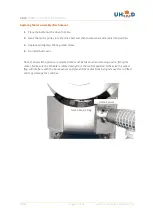
How to remove the Motor Assembly:
1.
Loosen the Belt Cover retaining screws.
2.
Remove the Belt Cover.
3.
Remove the Motor mount plate screw.
4.
Tilt the motor assembly towards the drive axis to release the belt tension and then remove
the motor assembly.
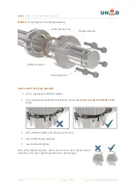
Note:
If any switch options are selected care must be taken when removing and re-fitting the
motor. Make sure the thimble is rotated away from the central position. Otherwise the sensor flag
Belt Cover Retaining
M3 Screws x 2
Belt Cover
Motor Mount Plate
M5 Screw
Содержание MD40 Series
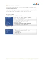
Страница 41: ...MD40 PRODUCT INSTRUCTION MANUAL MD40 Page 41 of 56 Author N Carapiet Revision 1 1 3 1 3 Switch Pin Out...
Страница 43: ...MD40 PRODUCT INSTRUCTION MANUAL MD40 Page 43 of 56 Author N Carapiet Revision 1 1 3 2 3 Home Sensor Pin Out...
Страница 47: ...MD40 PRODUCT INSTRUCTION MANUAL MD40 Page 47 of 56 Author N Carapiet Revision 1 1 Drawings Base Drive...
Страница 48: ...MD40 PRODUCT INSTRUCTION MANUAL MD40 Page 48 of 56 Author N Carapiet Revision 1 1 Dual Shaft...
Страница 49: ...MD40 PRODUCT INSTRUCTION MANUAL MD40 Page 49 of 56 Author N Carapiet Revision 1 1 Pneumatic Drive...
Страница 51: ...MD40 PRODUCT INSTRUCTION MANUAL MD40 Page 51 of 56 Author N Carapiet Revision 1 1 Side Mounted DC Motor Options...
Страница 55: ...MD40 PRODUCT INSTRUCTION MANUAL MD40 Page 55 of 56 Author N Carapiet Revision 1 1 NOTES...


