11
Description
COM
-
+
+
-
PS
Bat
Temp
AGM, Gel,Liquid
Solar
On/Off
CarBatt
+
-
-
+
-
+
X2
X3
X4
X1b
X1a
S1
X5
X6
H1
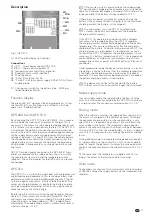
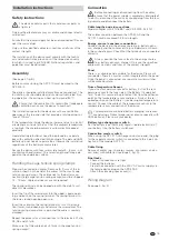
Fig. 1: APC 310
H1 LED function display (in housing)
Connections
X1a “PS” – Truma power supply APS 400-K
X1b “Bat”– Supply battery (battery II)
X2 Temperature sensor Battery I (optional)
X3 Separator main switch (optional)
X4 Panel (optional)
X5 “Solar” Solar Panel G1, G2
X6 “CarBatt” via Truma power supply APS 400-K to 13-pin
coupling plug
S 1 Change-over switch for the battery type – AGM, gel,
liquid (liquid electrolyte)
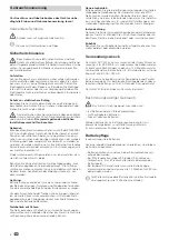
Function display
The green LED (H1) signalizes the charging process. Using
the red LED (H1), malfunctions are emitted as a flashing
code – see “Troubleshooting”.
APS 400-K with APC 310
By connecting the APC 310 to the APS 400-K, this is expand-
ed to include the function of an automatic charger. This is
necessary if the caravan is to be operated independently and
if it is to have its own supply battery (battery II). The APC 310
also provides the option of connecting two solar panels be-
cause of the built-in solar regulator, undervoltage monitoring
for the supply battery and a voltage booster. With an input
voltage of between 10 V and 14.5 V from the vehicle battery,
the voltage booster controls the output voltage so that the
supply battery always receives the optimum supply during
driving mode. It compensates any voltage fluctuations and
line losses.
APC 310 can be simply connected to the APS 400-K. New
cables are required for the supply battery, the solar system,
the separate master switch and the temperature sensor
(optional). The existing cables for the APS 400-K can remain
unchanged.
APC 310
The APC 310 is a state-of-the-art product with microprocessor
controlled charging equipment. This technology allows high
performance whilst remaining lightweight and small. Thanks
to the top quality electronics, it works highly efficiently. The
automatic charging process is gentle to the battery and pre-
vents damaging overcharging, which in turn significantly ex-
tends the service life of the battery.
By pressing the master switch on the control panel, the con-
nected 12 V consumers are switched ON and OFF. The 12 V
consumers are automatically switched off in battery mode
when the battery voltage undercuts 10.8 V (undervoltage
monitoring). The undervoltage cutoff is automatically reset at
a battery voltage > 12.5 V.
If the master switch is pressed when the undervoltage
monitoring is triggered, the consumers are switched on
again for 3 minutes (emergency-on mode). This function is no
longer possible if the battery voltage undercuts 10.0 V.
If there is excess power available it is used to charge the
battery. If the consumer current is higher than the maximum
charging current, the battery is not charged.
The microprocessor in the APC 310 automatically
assumes the battery management of the individual
charging current sources.
If the APC 310 is operated in conjunction with a tempera-
ture sensor for the supply battery, the APC 310 regulates
the charging current automatically depending on the battery
temperature. This ensures particularly effective and gentle
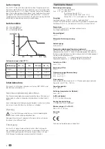
charging of the battery. At a battery temperature of 50 °C, the
charging process is interuppted. If a temperature sensor is
not used, the APC 310 regulates the charging process in the
same way as a battery temperature of 20 °C. For temperature-
controlled batery charging, we recommend using a Truma
temperature sensor, espcially with AGM batteries. Please ask
your dealer.
If the temperature inside the device increases due to a lack of
circulating air or due to the fact that the ambient temperature
is too high, the charging current is automatically reduced
gradually. If the maximum housing temperature is exceeded,
the battery charging process is interrupted.
The device may not be left connected to the battery
without solar or mains power for longer than two weeks.
Mains supply mode
In mains supply mode, the supply battery (Battery II) of the
caravan is automatically charged by the APC 310 when there
is surplus power. The maximum charging current is 10 A.
Driving mode
When the vehicle is moving, the supply battery (battery II) in
the caravan is charged via the vehicle‘s dynamo. To achieve
the optimum charging status for the supply battery, a volt-
age of 14.4 V is required. This voltage is not available in the
caravan due to line losses. The integrated voltage booster
controls the output voltage with an input voltage of between
10 V and 14.5 V so that the supply battery is always supplied
with 14.4 V. It compensates any voltage fluctuations and line
losses.
During driving mode, the integrated voltage booster receives
its supply voltage via the contact no. 10/11 on the coupling
plug. As long as the dynamo is running, the voltage booster
controls the output voltage to the supply battery to 14.2 V at
20 °C.
At the same time, the refrigerator is supplied with 12 V as
long as the motor of the towing vehicle is running.
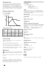
Solar mode
Connecting a maximum of two solar panels with total output
of 180 Wp charges the supply battery via the integrated solar
regulator.


