VMS-1655M
LIT-12013297
22
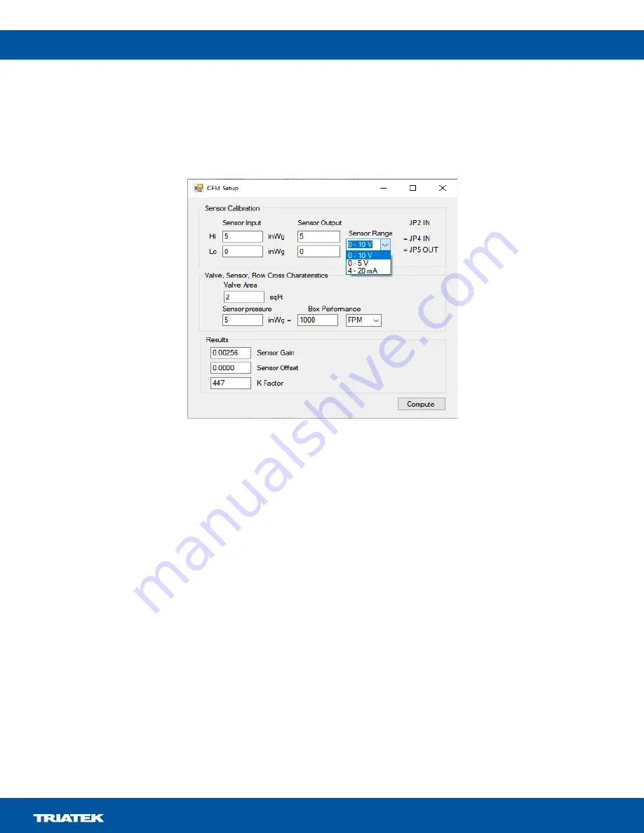
To set the calibration factors, gain, and offset to convert the sensor voltage to pressure, complete the following steps:
1. In the
CFM Settings
window, click the
Calc K P Gain/Offset
button and a
CFM Setup
window opens.
2. In the
CFM Setup
window, in the
Sensor Calibration
section, enter the features of the sensor that are in use.
3. From
Sensor Range
list, select the sensor range or signal type.
Note:
Make sure that the configuration of JP2, JP4, and JP5 links correspond to the information on the dialog.
4. Enter the output of the sensor for a specific duct velocity or cfm.
5. In the
Valve, Sensor, Flow Cross Characteristics
section, in the
Valve Area
field, enter the valve area in sq. ft.
6. From the Box Performance list, select
FPM
(velocity) or
CFM
(flow) as the interpretation of the sensor signal.
7.
Click
Compute
. The
Sensor Gain
,
Sensor Offset
, and
K Factor
compute. These values transfer to the appropriate fields in the
main tool display. The values you update highlight in yellow, as they do not pass to the controller yet.
8.
If the values are valid, click
Set K Factor
,
Set FP Offset,
and
Set FP Gain
to update the VMS with the settings.
9. Optional:
Click
Get CFM Val
to view the current CFM value.
Note:
To enable multiple cfm ranges for the 4 mA to 20 mA output signal, you must enter a CFM Scale factor. This value represents
what cfm the 20 mA signal output represents. For example, if you enter a scale factor of 1000, when the cfm is 0, the output is 4 mA,
when the cfm is 1000 cfm or above, the output is 20 mA, and when the cfm is 500 cfm, the output is 12 mA. In the CFM Setting window,
in the CFM Scale field, enter the scaling factor and click
Set CFM Scale
to communicate it to the VMS.
To calculate and generate the cfm and cfm 4 mA to 20 mA, the tool uses the following parameters:
•
Pressure reading: The pressure sensor calibration, gain, and offset.
•
K factor
•
Valve area
•
Scaling factor for cfm to 4 mA to 20 mA conversion
Figure 29: Sensor Calibration


