background image

VMS-1655M

LIT-12013297

19

4. Remove the cap from the sensor. 

5. Adjust the hood sash so that the face velocity is at a normal operating value or higher than 60 fpm. Wait until the value stabilizes.

6. Use an external velocity measuring instrument, for example, Shortridge, Alnor or equivalent, to measure the velocity at the face.

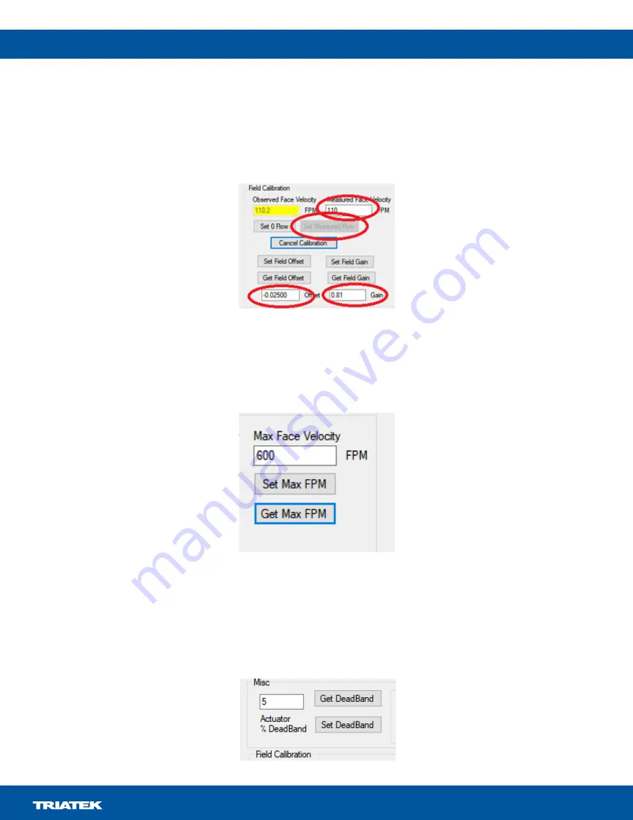
7. Enter the measured face velocity in the 

Measured Face Velocity

 field and click the 

Set Measured Flow

 button. The Offset and Gain fields

      now update and the data is sent to the sensor. The sensor is now calibrated to local conditions.

Figure 22: Measured Face Velocity

8. At any point, if you need to stop the procedure, click the 

Cancel Calibration

 button.

Face velocity

As the exhaust is at a constant volume, the face velocity varies as the sash moves up and down. When the sash reaches the closing position, 

the face velocity is very high. Use the 

Max Face Velocity 

setting to limit the internally used limit and the face velocity on display. 

Figure 23: Max Face Velocity

Click the 

Get Max FPM button 

to obtain the current setting. To change the current setting, enter a new value in the text field and click 

Set Max 

FPM

.

To prevent the baffle actuator from continually adjusting with fluctuating face velocities, You can set a deadband on the motor operation. 

The deadband is expressed as a percentage of motor movement. For example, a value of 5 indicates that the motor only moves if its 

positional requirement changes more than +5% or -5% from the current position. View or set this value with the 

Get


DeadBand 

and

 Set 

DeadBand

 fields.

Figure 24: DeadBand


Содержание VMS-1655M

Страница 1: ... of unit Optional display mode to show real time face velocity at main screen Graphical hood status display Audible and visual alarms Multi level password protection 1 analog input 0 VDC to 10 VDC 2 analog outputs actuator control exhaust air flow feedback BACnet MS TP network comms Real time view facility facilitates diagnostics during setup and commissioning Overview IMPORTANT Make all wiring co...

Страница 2: ... The alarm automatically resets when the unit senses that the fume hood face velocity returns to correct limits To mute the audible alarm touch the Alarm Audible button at the bottom of the touchscreen display The VMS 1655M provides an optional Analog Input that you can use to monitor the exhaust air flow of the fume hood that uses a third party flow pressure sensor with a 0 VDC to 10 VDC output Y...

Страница 3: ...itor 9 Calibrating vortex sensor 9 Configuring face velocity alarm setpoints 9 Changing fume hood operating mode 9 Setting a deadband 9 Changing network settings 10 Adding password security 10 Changing display settings 10 Built in diagnostics 10 Cleaning the display 11 Setup menu tree 12 Display setup 13 Module settings 14 Configuring display module settings 14 BACnet Objects 14 Wiring 15 Technica...

Страница 4: ...24 VAC 30 VA Class 2 Limited Energy or LPS for the controller and a separate 24 VAC 20 VA Class 2 Limited Energy or LPS for the actuator Failure to follow the wiring diagrams may result in damage to the actuator the transformer the controller or all devices and could void your warranty Note The Actuator is sold separately Risque de dommage à la propriété N utilisez pas un seul transformateur pour ...

Страница 5: ...ive pressure of the fume hood to accurately determine the face velocity at the sash opening The sensor must be located in a position that is least affected by turbulent air within the fume hood See Figure 10 See Figure 9 and Figure 10 for dimensions and suggested mounting arrangements of the flow sensor on the fume hood Note Be certain that sensor reference port is in laboratory room air If necess...

Страница 6: ...IGHT 4 REFERENCE PORT SIDE WALL TAP LOCATION VMS DEPTH 4 FUME HOOD WALL LINER FLEXIBLE TUBING TO ACTUATOR DIGITAL SENSOR 24 VAC POWER SUPPLY LINE VOLTAGE HEIGHT DEPTH Install the sensor in the hood s sidewall as shown in Figure 4 Note Height equals maximum sash opening measured from hood ceiling surface Depth equals measurement from sash window to rear baffle Figure 4 Vortex sensor location Figure...

Страница 7: ...e plate Flexible tubing cut to required length 3 supplied This port must be referenced to laboratory air for proper orienta on and should be located away from turbulence To VMS 1655M Interior of fume hood Exterior of fume hood Refer to wiring diagram on page 17 for power supply termina on VMS 1655M sensor interface cable 10 length pre wired at factory Vortex sensor mounting location Figure 7 Hood ...

Страница 8: ...late Mounting location Flexible tubing cut to required length 3 supplied Interior of fume hood Exterior of fume hood This port must be referenced to laboratory air for proper orienta on and should be located away from turbulence To VMS 1655M Refer to wiring diagram on page 17 for power supply termina on VMS 1655M sensor interface cable 10 length pre wired at factory Figure 9 Alternative vortex sen...

Страница 9: ... alarm setpoints Calibrating the vortex sensor The standard VMS 1655M comes pre configured and pre calibrated with a vortex sensor that is installed in the sidewall of the monitored fume hood After installation to begin the calibration of the vortex sensor complete the following steps 1 Touch the touchscreen display anywhere other than one of the hotspot locations to enter the Main Setup Menu See ...

Страница 10: ...ord the system prompts you to specify one of four access levels Unrestricted Standard Basic and Restricted All password entries save to non volatile memory In the event of a forgotten password a factory default password provides unrestricted access to the user menu system Consult with the factory for more information about this password The first user password automatically saves as unrestricted C...

Страница 11: ...ner acetone tolulene xylene propyl or isopropyl alcohol or kerosene Touching Status brings up a screen to quickly set the mode operation Touch ALARM AUDIBLE to set the mode of audible alarm This automatically reverts back to audible mode when alarm condition is removed Cleaning the display Figure 13 Hot Spot features of VMS 1655M touchscreen display Touch the unit name to bring up a keypad to ente...

Страница 12: ...VMS 1655M LIT 12013297 12 Setup menu tree Figure 14 Unit and system setup ...

Страница 13: ...VMS 1655M LIT 12013297 13 Display setup Figure 15 Display setup ...

Страница 14: ... Select OFF Invalid ON VMS 1655M 4 Operational Mode OFF Demo Mode ON Run Mode Push button Switch SW1 Reset Button Push button Switch SW2 Reserved Object instance Functional description Read or Write Analog inputs AI 1 Analog Input 1 Fume Hood Face Velocity Read only AI 2 Analog Input 2 Exhaust Air Flow Read only Analog outputs AO 1 Analog Outputs Actuator Position Read only Object instance Functio...

Страница 15: ...VMS 1655M LIT 12013297 15 Wiring Figure 16 VMS 1655M wiring ...

Страница 16: ...VDC to 10 VDC Power supply Class 2 24 VAC 10 30 VA universal 120 240 VAC to 24 VAC 60 50 Hz step down isolation transformer provided Cable type Belden 1325A Communications BACnet MS TP network Two wire twisted pair RS 485 signaling Cable type Belden 3107A Touch screen user interface LCD size 3 2 in diagonal LCD type Transmissive Resolution 240 pixels x 320 pixels portrait Viewing area 50 6 mm x 66...

Страница 17: ...rminal of the sidewall sensor and connect the yellow wire to the RS485 terminal 4 Remove the RS485 connection to the display module The display continually communicates with the sensor and disrupts the computer communications 5 Insert the USB connector of the cable into an available USB port on your computer and for first time connections wait until the USB driver installs 6 Open the computer Cont...

Страница 18: ...or parameter The greater the number is the larger the damping effect on the face velocity reading is and also the slower the response with changes in the face velocity is In most cases a starting value of 4 to 6 is sufficient Figure 20 Filter Factor You can calibrate the measured Face Velocity to conform with the specifics of the local fume hood The sensor uses a two point calibration The first po...

Страница 19: ...locity As the exhaust is at a constant volume the face velocity varies as the sash moves up and down When the sash reaches the closing position the face velocity is very high Use the Max Face Velocity setting to limit the internally used limit and the face velocity on display Figure 23 Max Face Velocity Click the Get Max FPM button to obtain the current setting To change the current setting enter ...

Страница 20: ...e face velocity is the highest 3 Wait until the face velocity stabilizes and either click the Get High Face Velocity button or manually enter the tool reported face velocity into the High Face Velocity text box 4 When the low sash position is complete move the sash to the highest operating height or highest expected point of use At this position the face velocity is the lowest 5 Wait until the fac...

Страница 21: ...a flow probe in the duct work This signal computes a cfm value that with scaling outputs on the 4 mA to 20 mA output signal Information and tools to set this up are available in the CFM Settings tab Figure 28 CFM settings The table in the tool updates with values that correspond to the high and low face velocities as well as the max face velocity Figure 27 Updated Hood Charactization table ...

Страница 22: ...e These values transfer to the appropriate fields in the main tool display The values you update highlight in yellow as they do not pass to the controller yet 8 If the values are valid click Set K Factor Set FP Offset and Set FP Gain to update the VMS with the settings 9 Optional Click Get CFM Val to view the current CFM value Note To enable multiple cfm ranges for the 4 mA to 20 mA output signal ...

Страница 23: ...ited States Canada This equipment has been tested and found to comply with the limits for a Class A digital device pursuant to Part 15 of the FCC Rules These limits are designed to provide reasonable protection against harmful interference when this equipment is operated in a commercial environment This equipment generates uses and can radiate radio frequency energy and if not installed and used i...

Отзывы: