background image

FITTING INSTRUCTIONS (cont.)

FILLING THE SYSTEM

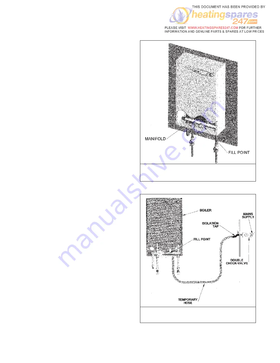
A filling point connection is provided on the front face of
the boiler manifold to facilitate the initial filling and
pressurising of the system via a hose connection
(supplied). Alternatively, a permanent filling-loop may be
employed.

Notes:

a)  Before filling, ensure that all fittings and joints 

have been made.

b)  Thoroughly flush out the system to remove any 

swarf and residue from the pipework and 
radiator(s).

c)  There must be no permanent connection between 

the boiler and the mains water supply.

Filling Method 1: Temporary Hose (Figs. 10/11)

1)  Connect a hose to the fill point on the manifold 

using the fittings supplied.

2)  Connect the other end of the hose to the mains 

water supply, ensuring that all safety valves are 
fitted in the run 

(Fig. 11)

to prevent system 

water entering the mains supply. Approved hose 
unions should be used on all connections.

3)  Open the fill point on the manifold 

(Fig. 10)

by 

turning the isolating knob anti-clockwise.

4)  Ensure all isolation valves to the system are open, 

that the bypass valve is closed, and that the 
automatic air vent contained within the boiler 
casings is open (turn the black cap on the device 
fully anti-clockwise).

5)  Switch on the mains supply to the boiler and test 

the pressure relief valve by continuing to fill until 
this device activates and releases water into the 
drain.

6)  Switch off the mains water supply.

7)  Using the pressure gauge on the front face of the 

manifold for reference, reduce the water content of 
the system until the pressure is indicated as 1.5 
bar.

8)  Thoroughly vent all parts of the system of air and, 

if necessary, readjust pressure back to 1.5 bar.

9)  Close off the fill connection on the manifold, remove 

the hose and close the automatic air vent.

10) Check all joints are water-tight before operating 

the appliance.

8

FIG. 10 - FILL POINT

FIG. 11 - FILLING METHOD 1


Содержание Aztec Gold

Страница 1: ...TRIANCO KM 59690 Electric System Boiler To be retained by the householder FITTING OPERATION INSTALLATION SERVICING INSTRUCTIONS ...

Страница 2: ...ed before despatch This appliance may contain some of the items below When working on the appliance it is the responsibility of the user engineer to ensure that any necessary personal protective clothing or equipment is worn appropriate to parts that could be considered as being hazardous to health and safety INSULATION AND SEALS Mineral fibre insulation is used on this appliance May be harmful if...

Страница 3: ...upply 6 Wiring Diagrams 6 7 Filling the System 8 9 Underfloor Heating Systems 10 OPERATING INSTRUCTIONS 11 Introduction 11 Boiler Controls 11 Indicator Lights 11 Safety Controls 11 External Controls 11 Cleaning Maintenance 11 Simple Fault Finding 12 TECHNICAL SPECIFICATION 12 INSTALLATION NOTES 13 Regulations Safety 13 Declaration of Conformity 13 Boiler Schematic 14 Boiler Components 15 SERVICE 1...

Страница 4: ...nsure that the area surrounding the boiler is kept free of items which would impede the good ventilation of the appliance e g towels linen c When siting the boiler take into account the need for future servicing Enough space should be provided at the front of the appliance to enable an engineer to adequately service and or replace components d The boiler is not to be fitted in a shower compartment...

Страница 5: ... the boiler 5 Install the heating system radiator towel rails etc in the desired positions as per the manufacturer s instructions A drain cock must be fitted at the lowest part of the system for ease of drainage See Fig 4 for a typical system layout IMPORTANT While the Aztec Gold is entirely suitable for use on heating systems which utilise plastic pipework the first 100mm from the boiler manifold...

Страница 6: ...l block is located within the casings at the top left hand side of the boiler Notes a This appliance must be earthed b It is recommended the boiler is fitted with an external control such as a room thermostat or programmer c If the water in the system is to be subject to freezing conditions during the pipework run the appliance should be fitted with a frost thermostat This will activate the boiler...

Страница 7: ...RUCTIONS cont ELECTRICAL SUPPLY cont 7 FIG 9 INTERNAL WIRING DIAGRAM FIG 9 INTERNAL WIRING DIAGRAM FIG 7 WIRING FOR PROGRAMMABLE ROOM THERMOSTAT FIG 8 WIRING FOR EXTERNAL PROGRAMMER ROOM THERMOSTAT FROST THERMOSTAT ...

Страница 8: ...pply Approved hose unions should be used on all connections 3 Open the fill point on the manifold Fig 10 by turning the isolating knob anti clockwise 4 Ensure all isolation valves to the system are open that the bypass valve is closed and that the automatic air vent contained within the boiler casings is open turn the black cap on the device fully anti clockwise 5 Switch on the mains supply to the...

Страница 9: ...ose from 4 onwards page 8 3 Once complete close all supply valves Notes a The filling method adopted must be in accordance with the Water Supply Regulations and the Water Bylaws b Approved hose unions should be used on all connections of this type COMPLETION 1 Replace the front casing of the boiler 2 Switch on the electricity supply to the boiler and external controls The appliance is now ready fo...

Страница 10: ...position Fig 14 Notes a The factory fitted safety high limit thermostat is set at 100 C and is suitable for use with radiator heating systems The additional high limit thermostat for exclusive use with underfloor heating systems is set at 60 C and must be fitted Failure to do so will result in damage to the floor surfaces b If the high limit thermostat operates often the temperature may be set too...

Страница 11: ...rmostat malfunction and the boiler overheat Note Should the appliance be used for supplying underfloor heating this thermostat must be replaced by the secondary stat supplied within the literature bag EXTERNAL CONTROLS Room Thermostat The room thermostat should not be positioned close to a source of heat such as a radiator or exposed to the sun as this would cause the heating to switch off before ...

Страница 12: ... illuminated Yes This indicates that the system pressure has dropped to below 1 bar Check the system pressure and if necessary re pressurise to above 1 bar No If all system controls room thermostat programmer have been checked please contact a service engineer for assistance IMPORTANT NOTE Electrical safety checks should only be carried out by a competent person Refer to page 16 for after sales se...

Страница 13: ...competent engineer should install the boiler and all wiring must be carried out in accordance with current I E E wiring regulations IMPORTANT This boiler is only to be fitted on fully pumped systems It is recommended that a scale inhibitor is added to prolong the life of the system Follow manufacturer s instructions for best practise on installation The appliance must not be operated until the sys...

Страница 14: ...14 FIG 17 BOILER SCHEMATIC ...

Страница 15: ...essel is suitable for systems with a water content of 28 litres including the boiler Should the system volume exceed this capacity an extra expansion vessel will be necessary An additional expansion vessel will also be necessary should the system pressure exceed 2 5 bar once the boiler reaches its highest temperature PRESSURE GAUGE The pressure gauge provides a visual indication of the system wate...

Страница 16: ...will result in a delay in the attendance of an engineer The serial number is located on the lower right hand side of the boiler casing IMPORTANT NOTES An on site charge will be made where a The service engineer finds no fault with the appliance b The cause of the breakdown is due to other parts of the heating system or equipment not provided by Trianco c The appliance falls outside the guarantee p...

Страница 17: ...s necessary The fuse is located above the PCB transformer and is rated at 630mA The fuse may have blown if the call terminal has been used to supply power to the ancillary controls FAULT 1st Red Light Flashing 1 Poor Electrical Connections The electrical connections between the element and the PCB may be faulty Check for loose or broken cables and for damaged terminals on both the heat exchanger a...

Страница 18: ...ms FRONT CASING REMOVAL Remove the 2 x screws from the top of the boiler and the single screw on the underside The door can then be removed safely PCB REPLACEMENT Fig 19 1 Ensure the electrical supply to the boiler is isolated 2 Remove the front casing as described above 3 Unscrew the 2 x fixing screws holding the PCB mounting bracket in position allowing the unit to be pulled forward 4 Holding th...

Страница 19: ...temperatures HEAT EXCHANGER REPLACEMENT Fig 22 1 Ensure the electrical supply to the boiler is isolated 2 Close the isolating valves to the boiler if fitted 3 Drain system via drain fill point on front of manifold 4 Disconnect element cables earth cable and thermistor cable Remove pump cable from terminal block 5 Disconnect compression fittings at bottom of heat exchanger on left hand side and flo...

Страница 20: ...solated 2 Close the isolating valves to the boiler if fitted 3 Drain system via drain fill point on front of manifold 4 Unscrew the expansion vessel and replace with a new unit re fitting in reverse order Ensure a suitable thread sealant is used on all joints 5 Re fill the system as described on pages 7 8 and open isolating valves PUMP HEAD REPLACEMENT Fig 25 1 Ensure the electrical supply to the ...

Страница 21: ...with underfloor heating systems 1 222592 222592 Wiring Harness 1 222578 222630 High Limit Thermostat Wiring Harness 1 222576 222576 Thermistor Cable 1 222548 222548 Pump 1 222557 222557 Expansion Vessel 1 222555 222555 Pressure Relief Valve 1 208069 208069 Pressure Safety Switch 1 222556 222556 Pressure Gauge 1 501808 501808 Automatic Air Vent 1 207296 207296 Door Casing Assembly White 1 222562 22...

Страница 22: ...e and the drawings or illustrations contained in it is vested in Trianco Limited and neither the brochure or any part thereof may be reproduced without prior written consent Trianco Limited s policy is one of continuous research and development This may necessitate alterations to this specification Instructions correct at time of going to print By appointment to H M Queen Elizabeth The Queen Mothe...

Отзывы: