


Network Configuration
90
Transputer Motherboard User Manual
TMB M 711
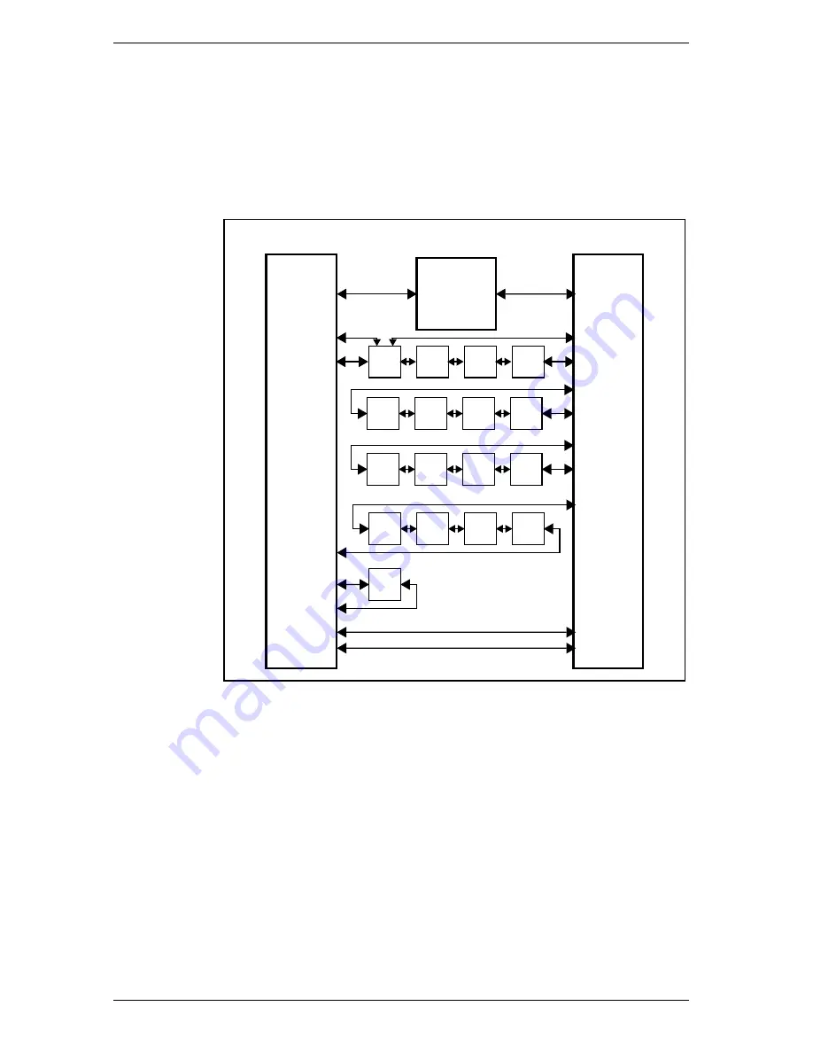
link between K1 and P2, this allows slot0 link3 to be taken off the
board, bypassing the electronic switches.
Figure 66 shows the main relations between P2, K1 and the link
switches.
0
1
2
3
4
5
6
7
8
9
10
11
12
13
14
15
T2
30b/29b
23b/24b
3/18
11/10
16c/15c
16a/15a
10a/9a
10c/9c
10b/9b
16b/15b
1/20
9/12
19/2
13/8
7/14
15/6
5/16
17/4
L 23
L 22
C004 switches
K1
P2
Figure 66. Network configuration
Содержание Transputer
Страница 1: ...Transputer Motherboard User Manual Ref TMB M 711...
Страница 8: ...vi Transputer Motherboard User Manual TMB M 711...
Страница 24: ...Summary 16 Transputer Motherboard User Manual TMB M 711...
Страница 64: ...The Edge Connector 56 Transputer Motherboard User Manual TMB M 711...
Страница 80: ...Examples 72 Transputer Motherboard User Manual TMB M 711...
Страница 122: ...Programming 114 Transputer Motherboard User Manual TMB M 711...
Страница 160: ...Examples 152 Transputer Motherboard User Manual TMB M 711...
Страница 192: ...Reference Manual Pages 184 Transputer Motherboard User Manual TMB M 711...
Страница 196: ...PC Host Interface 188 Transputer Motherboard User Manual TMB M 711...


