22
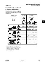
Installation - (2) ES300 Evaporators
Support Plates
Thermo King recommends securely installing steel support plates with
mounting studs (installer supplied) directly to the truck’s interior roof
structure to safely support the weight of the ES300 evaporators prior to
insulating and finishing the cargo area. The support plates should be
correctly located to position the evaporator the required distance from the
compartment front bulkhead wall to allow refrigerant and drain hose
connections. See “Tips for a Successful Installation” on page 8,
“Dimensions and Weight - ES300 Host Evaporator” on page 13 and
“Dimensions and Weight - ES300 Remote Evaporator” on page 14.
Preferred Installation Method
(with pre-installed support plates)
IMPORTANT: Be sure to install the correct evaporator in each
compartment. The HOST evaporator has drain pan heater wires while
the REMOTE evaporator does not.
1. Remove the plastic cover from each evaporator.
2. Position the HOST evaporator onto (installer supplied) ceiling
mounting studs in the Frozen Compartment.
•
Install washers and locking nuts and tighten hardware securely.
3. Position accumulator assembly at the rear of REMOTE evaporator:
•
Connect the supplied 7/8” tube assembly with o-rings to the mating
fitting inside the evaporator.
•
Secure the accumulator to the rear of the evaporator with supplied
hardware and tighten securely.
4. Position the REMOTE evaporator onto (installer supplied) ceiling
mounting studs in the Fresh Compartment.
•
Install washers and locking nuts and tighten hardware securely.
NOTE: The covers for both evaporators will be installed later.
Alternative Installation Method
(without pre-installed support plates)
1. Locate and mark the center line (C/L) of the interior compartment
ceiling.
2. HOST evaporator - Allow a minimum distance of 152 mm (6.00 in.)
from the cargo area wall to the rear of the evaporator for refrigerant
hose and drain hose connections.
REMOTE evaporator (with accumulator assembly) Allow a
minimum distance of 152 mm (6.00 in.) from the cargo area wall to the
rear of the accumulator assembly for refrigerant hose and drain hose
connections.
3. Position each evaporator up to the ceiling and mark the location of the
four mounting holes. NOTE: Be sure the evaporator’s air outlet is
facing the correct direction for proper airflow.
4. Drill four 5 mm (0.472 in.) mounting holes into the ceiling and loosely
install the supplied 1/4” lag bolts and washers.
5. Remove the plastic cover from each evaporator.
6. Position accumulator assembly at the rear of REMOTE evaporator:
•
Connect the supplied 7/8” tube assembly with o-rings to the mating
fitting inside the evaporator.
•
Secure the accumulator to the rear of the evaporator with supplied
hardware and tighten securely.
7. Apply neutral/alcohol cure silicone sealant (installer supplied) per the
sealant manufacturer’s instructions to the top surface area of the
evaporator.
8. Install the HOST evaporator onto the ceiling of Frozen Compartment
with the 1/4” lag bolts and washers and hand tighten bolts securely.
9. Install the REMOTE evaporator onto the ceiling of Fresh
Compartment with the 1/4” lag bolts and washers and hand tighten
bolts securely.
NOTE: The evaporator covers will be installed later
Содержание Thermo King ES300
Страница 12: ...11 Required Tools ...
Страница 18: ...17 Dimensions Condenser Module Mounting Holes ...
Страница 19: ...18 Dimensions HMI A 140 mm 5 50 in B 46 mm 1 80 in C 12 mm 50 in ...
Страница 20: ...19 BLANK PAGE ...
Страница 24: ...23 Installation 2 ES300 Evaporators Alternative Installation Method Preferred Installation Method ...
Страница 26: ...25 Installation Refrigeration Module Alternative Installation Method Preferred Installation Method ...
Страница 28: ...27 Installation Power Pack Module Alternative Installation Method Preferred Installation Method ...
Страница 30: ...29 Installation Condenser Module Preferred Installation Method Alternative Installation Method ...
Страница 38: ...37 Important Suction Line Routing and P Trap Formation NOT ACCEPTABLE From Unit ...
Страница 40: ...39 Installation Refrigeration Tubes to Compressor ...
Страница 46: ...45 System Leak Check and Evacuation ...
Страница 48: ...47 Installation Electrical Connections ...
Страница 50: ...49 Electrical Connections Evaporator s ...
Страница 52: ...51 Installation Standby Power Receptacle ...
Страница 54: ...53 Installation Drain Hoses REMOTE Evaporator HOST Evaporator Defrost Heater Wires ...
Страница 56: ...55 Installation HMI ...
Страница 62: ...61 System Charging AMOUNT OF REFRIGERANT PER MODEL Model 50 5 00 lbs ...