


Installation
18
CVRF-SVN005C-EN
7. Condenser discharge refrigerant temperature sensor
4R16 (optional). This sensor is only shipped if Hot gas
bypass or Enhanced Protection packages were ordered
and are to be installed.
8. Bearing temperature sensors: inboard-4R1, outboard-4R2
(optional). These sensors are only shipped if Enhanced
Protection package was ordered and is to be installed.
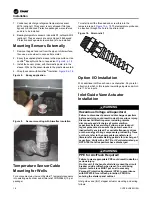
Mounting Sensors Externally
1. Remove the paint and rust from the pipe or chiller surface;
then use a wire wheel to expose bare metal.
2. Epoxy the supplied plastic sleeve to the pipe surface. Use
Loctite
®
Epoxy Quick Set, or equivalent,
3. Install the sensor probe, with thermastic paste, into the
sleeve. Wire tie the sensor leads to the plastic sleeve tab.
4. Wrap the sensor with Armaflex
®
insulation,
.
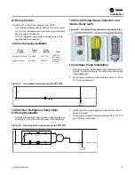
Figure 8.
Epoxy application
Figure 9.
Sensor mounting with Armaflex insulation
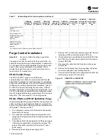
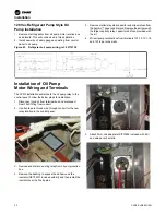
Temperature Sensor Cable
Mounting for Wells
For a convenient way to mount Symbio™ temperature sensors
into existing wells, order and strain relief CON00849 (10 per
package).
To install insert the threaded end screw this into the
temperature well,
. The temperature probe can
be inserted through the hole in the strain relief.
Figure 10. Strain relief
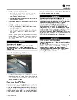
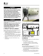
Option I/O Installation
Wire additional LLIDs as shown on schematics. Pay careful
attention to which LLIDs require low voltage inputs and which
are 115 Vac inputs.
Inlet Guide Vane Actuator
Installation
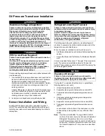
WARNING
Hazardous Voltage w/Capacitors!
Failure to disconnect power and discharge capacitors
before servicing could result in death or serious injury.
Disconnect all electric power, including remote
disconnects and discharge all motor start/run
capacitors before servicing. Follow proper lockout/
tagout procedures to ensure the power cannot be
inadvertently energized. For variable frequency drives
or other energy storing components provided by Trane
or others, refer to the appropriate manufacturer’s
literature for allowable waiting periods for discharge of
capacitors. Verify with a CAT III or IV voltmeter rated per
NFPA 70E that all capacitors have discharged.
WARNING
PPE for Arc/Flash Required!
Failure to wear appropriate PPE could result in death or
serious injury.
On this unit, if the handle shield is cracked the circuit
breaker could arc/flash when reset. To avoid being
injured, technicians MUST put on all necessary
Personal Protective Equipment (PPE), in accordance
with NFPA70E for arc/flash protection, PRIOR to
entering the starter panel cabinet.
Inlet guide vane (IGV) stepper actuator mounting and wiring
follows:
Содержание Symbio CVRF
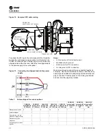
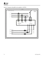
Страница 43: ...Figure 57 Dual CT wiring example Starter Work CVRF SVN005C EN 43...
Страница 47: ...Notes CVRF SVN005C EN 47...


