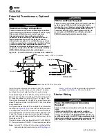
Trane Symbio CVRF Скачать руководство пользователя страница 33

CVRF-SVN005C-EN

33 

Starter Work

WARNING

Electrical Fault!

Failure to follow instructions below could result in 

death or serious injury from burns or electric shocks. 

Tracer® AdaptiView™ wye-delta starter timing is 

different from UCP2 wye-delta starter timing. 

Symbio™800 uses contactor auxiliary switches to 

prevent simultaneous closure of run and shorting 

contactors. Starter wiring changes MUST be made per 

drawings listed in 

“Wiring Diagram Matrix,” p. 46

 to 

prevent an electric fault condition.

WARNING

Proper Field Wiring and Grounding 

Required!

Failure to follow code could result in death or serious 

injury. 

All field wiring MUST be performed by qualified 

personnel. Improperly installed and grounded field 

wiring poses FIRE and ELECTROCUTION hazards. To 

avoid these hazards, you MUST follow requirements for 

field wiring installation and grounding as described in 

NEC and your local/state/national electrical codes.

Important:

Symbio™800 requires a closed transition 
starter. If the existing starter is an open 
transition style, it must be replaced.

Starter Control Planning

WARNING

Electrical Fault!

Failure to follow instructions below could result in 

severe injury and equipment damage. Tracer® 

Adaptiview™ requires the use of contactor auxiliary 

switches to prevent simultaneous closure of run and 

shorting contactors. Existing mechanical interlocks will 

wear out and fail if not used in combination with 

contactor auxiliary and result in the contactors 

exploding. Starter wiring documented in 

“Wiring 

Diagram Matrix,” p. 46

, MUST be made to prevent an 

electrical fault condition.

The starter work required varies significantly from one 
application to the next. These instructions are somewhat 
generic. Detailed plans have to be worked out using these 
instructions as a guide along with your specific starter wiring 
and hardware information. Use the existing starter wiring and 
the Symbio™ ship with starter wiring diagrams for determining 
your exact wiring.
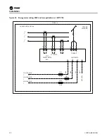
The 3-phase starter module can control the starter using one 
of two methods:

– Direct control of each starter contactor

– Pilot relay interface to the existing contactors

Both methods result in similar operation of the starter. When 
the module is wired for direct control all functions of the dry run 
test can be performed. The pilot relay method must be used 
when the contactor coils are voltages other than 115 Vac. If 
both direct control or pilot relay control can be used on your 
application, select the method that best suits your needs.
The wiring diagrams for direct control are referenced i

“Wiring 

Diagram Matrix,” p. 46

. Also use 

“Wiring Diagram Matrix,” 

p. 46

 for pilot relay diagrams, sometimes referred to as 

customer supplied starter wiring. Pilot relays are field provided.
Retain any special options and determine how they might fit 
into the new method of control. Keep a detailed record of your 
revisions to help with future troubleshooting.
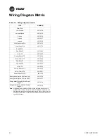
Starter panel conversion varies with existing starter type and 
starter control voltage. For reference, 

“Wiring Diagram Matrix,” 

p. 46

 lists the electrical schematics for typical Symbio™ wiring 

for wye-delta, across-the-line, primary reactor, auto 
transformer, and solid-state starters.

Important:

To ensure that the starter panel retrofit 
procedure is performed properly, carefully 
review the instructions in this section. Record a 
detailed description of all electrical changes 
made during the starter retrofit process. Be 
sure to add a copy of this report to the chiller 
record file for future reference.

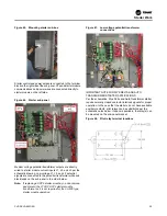
The instructions that follow detail the rework of a typical wye-
delta starter for direct control by Symbio™ and the starter 
module LLID.
While this conversion procedure specifically applies to wye-
delta starters, it can be adapted to successfully modify other 
types of starters for operation with a Symbio™ starter module.

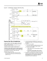
Starter Sub-Box Installation

The starter sub-box is intended for remote mount starter 
installations where due to their custom nature there isn’t room 
for mounting the sub-panel in the starter enclosure and/or such 
an installation inside the enclosure would be inconvenient or 
un-safe. 
As the Symbio™ starter sub-panel provides a direct 
replacement for a UCP2 starter module it is expected that the 
sub-box will be rarely required, however a description of its 
installation is provided in case it is needed.   
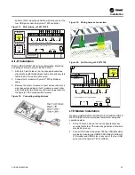
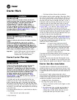
1. Installing the Starter Panel sub-box
2. Mounting of the optional starter sub-box:

a. Remove door from box. Door can be hinged on either 

side of cabinet.

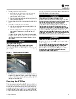
b. Mount starter sub-box on starter panel as shown in 

Figure 45, p. 35

 using hardware provided. When 

drilling holes in starter cabinet, take care to avoid 
getting metal shavings into starter cabinet.

Содержание Symbio CVRF

Страница 1: ...apart from the Symbio control panel SAFETY WARNING Only qualified personnel should install and service the equipment The installation starting up and servicing of heating ventilating and air condition...

Страница 2: ...that is used in these service procedures In addition some states or municipalities may have additional requirements that must also be adhered to for responsible management of refrigerants Know the ap...

Страница 3: ...his document and the information in it are the property of Trane and may not be used or reproduced in whole or in part without written permission Trane reserves the right to revise this publication at...

Страница 4: ...Purge 21 PRGD PRGG and PRGF EarthWise Purge 21 LONTALK Option Installation 22 Communication Option Installation 22 Wi Fi Installation 22 Air Fi Installation 23 LTE Modem Installation 23 Communication...

Страница 5: ...s before you attempt to perform the control system conversion Application Guidelines This Symbio control package is specifically designed to upgrade the controls of CVHE CVHF and CHVG water cooled chi...

Страница 6: ...or chillers KIT18458 KIT ECHELON MODULE FIELD INSTALL KIT DAIO Dual analog input and output BRD04875 DBI Dual low voltage binary input BRD04873 DHVBI Dual high voltage binary input BRD04874 DRO Dual r...

Страница 7: ...LID Name Description Part Number Table 4 Field installed LLIDs for various options DBI DHVBI DBO HPRO QRO DAIO LON IGV PS 475 PSI Temp Sensor PS 0 to 50 or 475 PSI Starter Module Color Display WiFi Ai...

Страница 8: ...eplacement This is a partial list in addition to normal service tools and hardware Type A to Type B USB cable Computer having Tracer TU version 13 0 or newer Digital multi meter with phase detection c...

Страница 9: ...ssure transducers on the copper oil lines Table 5 Fusing added for 2F1 2F2 and 2F3 as needed for optional PT transformers Voltage Vac Fuse A Voltage Vac Fuse A 200 1 600 1 230 1 2400 1 380 1 4200 1 46...

Страница 10: ...None A 480 Vac or less B Greater than 600 Vac C 2300 2400 Vac D 3300 Vac E 4200 Vac F 6600 Vac 50 Hz Digit 10 11 Design Sequence A0 1st Design sequence Digit 12 Actuator 1 Stepper actuator 2 Pulse act...

Страница 11: ...B Starter module with plate for low voltage remote starter C Starter module with plate for unit AFD D Starter module with plate for remote AFD E Starter module with plate for medium voltage unit star...

Страница 12: ...trol panel disconnect switches and secure them in that position WARNING Hazardous Voltage w Capacitors Failure to disconnect power and discharge capacitors before servicing could result in death or se...

Страница 13: ...1 to H2 If you have wired a temporary thermostat and 115 Vac power source to the oil heater leads wait to connect these wires until the Tracer AdaptiView retrofit is complete to avoid too much cooling...

Страница 14: ...the control panel select the side that s most suitable for your specific application Note There is a production display arm bracket BRK04345 provided that where applicable can be mounted to the existi...

Страница 15: ...es not spring up or sag down out of the position it is moved to by the operator CAUTION Tension in Display Support Arm Failure to follow instructions below could result in unexpected movement of the s...

Страница 16: ...s labeled with loosen tighten or indicators Figure 7 Joint locations on the display arm 2 Joint 3 has a 6 mm hex screw controlling the tension on a gas spring which allows the Tracer AdaptiView displa...

Страница 17: ...commended that existing bulb wells be used Installing new wells would necessitate opening the chiller to atmosphere WARNING Refrigerant under High Pressure Failure to follow instructions below could r...

Страница 18: ...the hole in the strain relief Figure 10 Strain relief Option I O Installation Wire additional LLIDs as shown on schematics Pay careful attention to which LLIDs require low voltage inputs and which ar...

Страница 19: ...bus on the chiller The Symbio retrofit kit includes a general wire kit that has several different types of wires An example of a wiring layout can be seen in Figure 12 p 20 Each application will vary...

Страница 20: ...the correct cables so that you don t have any open plugs when finished Avoid placing wire ties directly over plug connectors This may press on the locking mechanism and over time the plugs may release...

Страница 21: ...LID 3A6 will not be needed disconnect and remove 2 The condenser saturated refrigerant temperature LLID purge liquid temperature will not be needed disconnect and remove 3 The existing 120 27 Vac tran...

Страница 22: ...N005C EN LONTALK Option Installation Symbio 800 system uses a U60 LON module through the USB connection instead of the LCI C LLID 1 Install the U60 LON module KIT18458 KIT ECHELON MODULE FIELD INSTALL...

Страница 23: ...e 20 Air Fi wiring ref 50712738 LTE Modem Installation Modem part is MOD03184 MODULE CELLULARLE USB 2 9 METER CABLE Refer to provided literature for setup and operation details 1 Drill a 1 36 inch hol...

Страница 24: ...tallation standard application need to field drill a 1 09 inch hole on side of box for a snap bushing This bush can be replaced as field straight connector and conduit 3 4 inch size as NEMA 4 applicat...

Страница 25: ...re two transducer 0185 3475 0100 provided per heat exchanger Field connect by male to 2 female 1000mm branch cable CAB01147 which provided in package Figure 26 Standard accuracy option Mounting of Flo...

Страница 26: ...ovided Meter Option The high accuracy customer provided meter option provides an analog input output LLID to monitor a customer provided high accuracy meter 0 10 Vdc or 4 20 mA outputs Rosemont etc Th...

Страница 27: ...following Wire AWG From To 14B 16 1A29 J3 2 1X1 21 2K 16 1A29 J3 1 1X2 10 4 4 RED J11 1 J1 1 OPTIONALWA TER FLOW METE R CUSTOMER PROVIDE 4 20MA INPUT 1A21 DUAL ANALOG I O OPTIONA L INPUT 1 OUTPUT1 2...

Страница 28: ...ent grade accuracy power volts and amps monitoring of Symbio controls installations It has 1 accuracy for measuring both real power and energy and reactive power and energy All data measured by the me...

Страница 29: ...minated at the Modbus distribution terminal 1X3 beside Symbio 800 using the 3 poles connector which provide in energy meter kits Figure 36 Distribution terminal Figure 37 Modbus wiring ref 50712738 48...

Страница 30: ...0 2T51 2T52 LINE 99 TO 1X3 WHT BLK WHT BLK WHT BLK RED BLK BLU YEL ORG BRN WHT 2F54 2F52 2F53 0 5A 0 5A 0 5A DETAIL A ENERGY METER OPTION NOT USED WB22 X1 X2 X1 X2 X1 X2 G MODBUS VOLTINPUTS L1 L2 L3 N...

Страница 31: ...e start relay start capacitor and related wiring from Symbio panel and discard These items will not be used in this application 2 Wire oil pump contactor coil between terminals 1X1 14 and 1X1 6 as per...

Страница 32: ...and 1X1 6 per schematic Figure 43 Refrigerant oil pump wiring ref 50712738 Installation of Oil Pump Motor Wiring and Terminals The CVRF installation will relocate the oil pump relay to the control pa...

Страница 33: ...of the dry run test can be performed The pilot relay method must be used when the contactor coils are voltages other than 115 Vac If both direct control or pilot relay control can be used on your app...

Страница 34: ...needed A description of the sub panel s types and uses is below Table 8 Sub panel types Model Digit 33 Application Part Number Description Starter Mount Type PTs Configuration Selection FACT FCOD E St...

Страница 35: ...e and black leads on the sub panel in the order below Note If replacing a UCP2 starter module you can remove and discard the 27 VAC UCP2 starter module transformer as it is not required for the CH530...

Страница 36: ...Figure 49 Pilot relay switching configuration Figure 50 Wye delta interlock and pilot relay wiring Starter Work 36 CVRF SVN005C EN...

Страница 37: ...as follows 1 Remove existing UCP2 module keeping potential transformers and secondary current transformers if needed for reuse 2 Install existing potential transformers on lower panel if required and...

Страница 38: ...to refer to the wiring diagrams listed in Wiring Diagram Matrix p 46 as you review the following instructions The wire numbers and component designations indicated in these steps appear in these figu...

Страница 39: ...ications to starter module b For remote mount AFDs i Wire per schematic starter module will be powered by sub panel power supply ii Use existing communications cable to connect Symbio communications b...

Страница 40: ...and its orientation The polarity dot should face incoming power in other words towards the disconnect Figure 55 Current transformer single turn down Wire the leads from the CT male quick connects to t...

Страница 41: ...ordered secondary CTs In this case two CTs are used per phase to either achieve the necessary turn down or for metering convenience The first stage consists of either the X13580271010 TRR01287 X135802...

Страница 42: ...600 05 00 600 2 5 1 432 336 504 TRR00451 TRR00975 700 05 00 700 2 5 1 504 384 576 TRR00451 TRR00975 800 05 00 800 2 5 1 576 480 720 TRR00451 TRR00975 1000 05 00 1000 2 5 1 720 480 720 TRR00655 TRR0097...

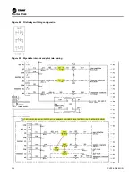
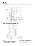
Страница 43: ...Figure 57 Dual CT wiring example Starter Work CVRF SVN005C EN 43...

Страница 44: ...ater than 600 Vac a large medium voltage PT is used to step from line voltage to 115 Vac and a second PT steps the voltage to less than 30 Vac The large PT is a three phase type except for the 6600 Va...

Страница 45: ...ering the starter panel cabinet NOTICE Module Damage Failure to follow the following instruction could result in equipment damage Do NOT connect the secondaries of the line to 120 Vac potential transf...

Страница 46: ...50710524 Primary Reactor CS 50710525 Auto X Former CS 50710527 Starter Subpanel VFD 50711536 Energy Meter Option 480V and Low 50712756 Energy Meter Option 575 and 600V 50712757 Energy Meter Option MV...

Страница 47: ...Notes CVRF SVN005C EN 47...

Страница 48: ...re committed to using environmentally conscious print practices Trane by Trane Technologies NYSE TT a global climate innovator creates comfortable energy efficient indoor environments for commercial a...

Отзывы: