


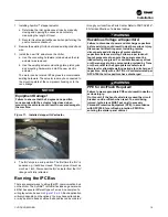
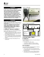


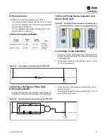


Figure 12. Sample of IPC cable routing
Installation
20
CVRF-SVN005C-EN
To connect the IPC bus to the control panel LLIDs, thread the
bus into the control panel via a knockout or other entry. The
CAB01155 connector has a female plug on one end and four
stripped leads on the other end. Attach the four stripped leads
to the power supply in the control panel.
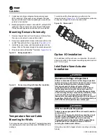
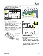
Figure 13. Connecting the stripped leads to the power
supply
Notes:
•
R. Red wire for 24 Volts direct current
•
Bk. Black wire for ground
•
Bl. Blue wire for IPC+ connection
•
Gr. Gray wire for IPC- connection
Make sure all devices and LLIDs are connected together in
some way. Use the correct cables so that you don’t have any
open plugs when finished. Avoid placing wire ties directly over
plug connectors. This may press on the locking mechanism
and over time the plugs may release.
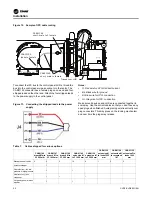
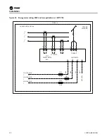
Control Panel
CAB01155
leads to female
CAB01149
short, male to female
CAB01146
short, male to 2 female
Transducer LLID
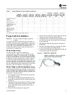
Table 7.
Cables shipped for various options
CAB01146
branch M
(a)
to
2F 500 mm
CAB01147
branch M to
2F 1000 mm
CAB01148
branch M to
3F 500 mm
CAB01149
extension M
to F 1000 mm
CAB01150
extension M
to F 2000 mm
CAB01152
extension M
to leads 1000
mm
CAB01154
extension M
to receptacle
1M
CAB01155
extension F to
leads 1000
mm
Standard panel cables
5
5
5
10
9
1
2
2
Actuator-stepper
1
Oil protection—full, low
pressure or high pressure
1
1
Heat recovery / aux
condenser
1
1
1
Hot gas bypass—electric
actuator
1
1
Содержание Symbio CVRF
Страница 43: ...Figure 57 Dual CT wiring example Starter Work CVRF SVN005C EN 43...
Страница 47: ...Notes CVRF SVN005C EN 47...


